
TD-150-BLE: Difference between revisions
| Line 788: | Line 788: | ||
=== '''<big>Alternative sealing of a current sample sensor</big>''' === | === '''<big>Alternative sealing of a current sample sensor</big>''' === | ||
Also included with the sensor of the current sample is an alternative seal if a numbered seal is required. | Also included with the sensor of the current sample is an alternative seal if a numbered seal is required. | ||
* It is necessary to pass the cable through the hole in the sensor cover [[Файл:Альтернативная пломбировка проводного дут шаг 1.png|580x580пкс]] | * It is necessary to pass the cable through the hole in the sensor cover [[Файл:Альтернативная пломбировка проводного дут шаг 1.png|580x580пкс]] | ||
Revision as of 15:17, 4 July 2024
Definition and purpose of the sensor

High-precision fuel level sensors (FLS, also meters or sensors) of the Escort brand are designed to determine the filling level of petroleum products in fuel tanks, reservoirs and storage tanks. The TD-150-BLE meter (sensor) is used in transport technology as a fuel level meter, in industry - as a level meter for any light petroleum products. Escort FLS measurement type is capacitive. Its readings are based on the dielectric constant of the medium in which it operates; in this case, the medium is various types of light petroleum products (gasoline, diesel, kerosene, motor oil).
The TD-150-BLE is a wired FLS with bluetooth transmission and configuration capability. The sensor data is transmitted in the form of Bluetooth packets in Advertising mode; the frequency of data sending is every second. The frequency of fuel level sensor measurement is also every second.
More detailed technical characteristics are presented in the тех.паспорте устройства.
Basic terms and concepts
Fuel level sensor (FLS) - device which is used for measuring fuel level.
Serial number - code consisting of letters and numbers assigned to a device (sensor).
CNT - an oscillatory circuit, thanks to which the basic level of filling of the sensor measuring tubes with fuel is calculated. This level is converted to a final value determined by the data interface.
Протокол передачи данных - набор определённых правил или соглашений интерфейса логического уровня, который определяет обмен данными между различными программами или устройствами. Для ТД-150 основным протоколом передачи является LLS по интерфейсу RS-485 и по интерфейсу Bluetooth для передачи пакетов данных используется протокол Escort BLE.
Sensor's name - sensor's designation among BLE devices consisting from two letter from the sensor's model name and six last digits from the serial number; E.g. TD_100100;
MAC-address - unique identifier assigned to every active device. Used to recognize devices in the network.
Data packet - is a set of parameters transmitted by a device equipped with a Bluetooth transmitter, the structure of which is determined by the data transfer protocol.
Advertising mode - is a data transfer mode in which the device “distributes” data packets at a certain frequency, regardless of the presence of a device receiving the data.
Connection mode - is a data transfer mode in which the transmitter waits for a connection to the receiving device in order to begin transmitting data packets.
База BA-BLE - is a device that relays data transfer and converts it from a Bluetooth packet into a data packet transmitted via the RS-485 interface in accordance with the LLS protocol.
Data transfer mode - this is a type of boundary between two objects or nodes, which are regulated by a special accepted standard and implemented using established methods, tools and rules. TD-150 has the following operating modes:
- RS-485 (Passive and Active)
- Analog
- Frequency
Interface - a physical connection method and/or a set of software tools that allows data to be transferred between two or more devices.
RS-485 - digital data transmission mode. The sensor waits for a corresponding request from the receiving device. Works using the LLS protocol. Based on CNT, a value is generated in conventional units of the selected range (1-1023 units or 1-4095 units)
Converter - digital converter RS-485 to USB (С200М или С200М2) for configuring wired sensors.
Active (periodic) RS-485 - operating mode in which the sensor, without waiting for a request from the receiver, itself transmits packets with command data within 2 seconds.
Analog - mode in which a corresponding voltage is generated based on the CNT in the approximate range of 0.2-9V.
Frequency - mode in which the corresponding frequency in Hz is generated based on the CNT (301-1323 Hz with a value range of 1-1023; 301-4395 Hz with a value range of 1-4095).
Navigation terminal - the main element of the system for monitoring the operation of transportation carried out by means of satellite communication. Without it, it is impossible to control transportation, to determine the coordinates of the vehicle location. It collects information from sensors and on-board system of the vehicle, and then transmits it to the device/server, which belong to the controlling specialist.
Preparation
Preparing the Tank
To prepare the tank you should:
- Empty the tank, clean and dry if necessary
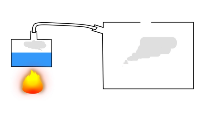
- Remove fuel vapors and air from the tank (especially for a gasoline tank, but in the case of a diesel engine, this procedure should not be neglected, since gasoline could be added to the diesel); to do this, you can heat water to boiling point and direct the resulting steam into the tank or use carbon dioxide so that it displaces fuel vapors and air; ensure that any open flame sources are sufficiently far away from the fuel tank
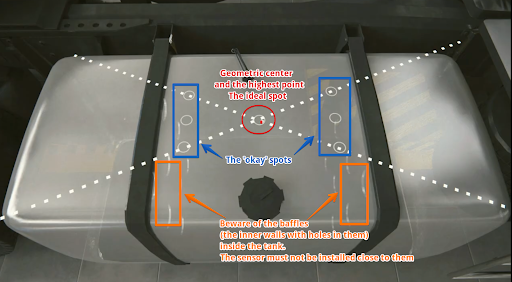
- Find the geometric center of the tank and drill a hole in it using a ø3mm drill bit. Then, using a piece of stiff wire, examine the tank for the presence of partitions in it
Choosing a location for installing the FLS 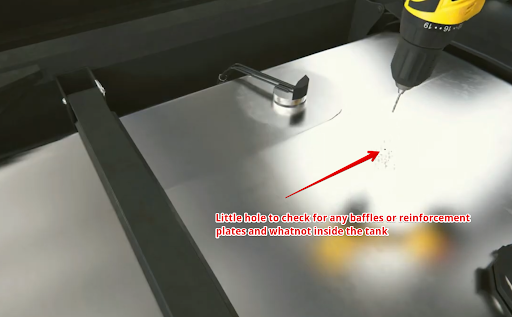
Drilling the tank and subsequent examination of the tank for the presence of partitions - If the space inside the tank in the selected location is free, drill a ø 35 mm hole using a bimetallic bit; When drilling, keep the bit tilted slightly to prevent the cut section from falling into the tank. Use a magnet to catch chips and prevent them from getting into the tank.
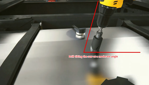
Drilling a hole at an angle 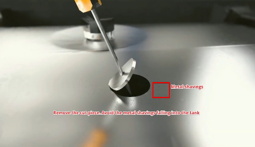
Removing a Drilled Disc - If it is impossible to install the sensor in the geometric center of the tank, try choosing another location as close as possible to the geometric center of the tank; this point should coincide with the place where the height of the tank is maximum. This way you reduce the risk and amplitude of level fluctuations associated with fuel movement while driving.


Why should the sensor be mounted in the geometric center of the tank?
The highest point must be chosen so that the sensor can measure the level of all the fuel inside the tank without any blind spots.
The fuel level readings from a sensor installed in the center of the tank will be least affected by movement and fuel overflow in the tank.
If it is not possible to install the sensor in the center of the tank, consider installing two sensors diagonally at two corners. When fuel flows to one side of the tank, the level on the corresponding sensor will rise, and on the opposite side, the level will correspondingly decrease, while the average level will remain unchanged.
Видео пример важности установки датчика по геометрическому центру бака. без|мини|805x805px|Положение датчика и перетекание топлива
Attention: Before starting the calibration, the vehicle/fuel tank must be positioned flat in relation to the horizon, i.e. on a level surface without a slope.
If the tank has an irregular geometric shape, the sensor must be installed at the maximum depth of the tank, closer to the geometric center.
без|мини|737x737пкс|Датчик установлен в самое высокое место бака
When installation in the center is impossible - two or more FLS.
To increase accuracy and reduce level fluctuations, install two sensors in one tank. This solution is mainly used in tanks with a capacity of more than 600 liters and having a length of 1500 mm. Sensors must not be installed close to the walls of the tank.
Also, two or more sensors should be installed if it is not possible to install the sensor in the center of the tank and (or) the tank has an elongated shape, i.e. The length of the tank is significantly greater than its height. без|мини|748x748пкс|Два датчика установленных по диагонали Note. Installing a single sensor in an elongated tank will allow you to detect drains and refills. But increased level fluctuations while driving may not allow the monitoring platform to correctly read fuel consumption. Therefore, installing two sensors is preferable.
Preparing the sensor
Preparing the sensor tubes
Before calibrating the sensor, you should determine the future length of the measuring tubes in accordance with the height of the tank and cut or extend them. The length of the tubes should be calculated according to the following formula:
L = H - 15 mm,
where L - tubes length after changing the length
and
H - height of the tank at the installation point.
ATTENTION!!! The minimum length of the tubes should not be less than 15 cm (150 mm). Otherwise, it will most likely not be possible to obtain adequate graphics. The maximum length of the tubes can reach 6m..
без|мини|843x843пкс|Измерение высоты бака без|мини|846x846пкс|Измерение длины трубок Use a hacksaw to cut the tubes. When sawing, be careful not to damage the connection of the tubes to the circuit board inside the sensor head and to prevent metal shavings from falling into the tubes. без|мини|Обрезка трубок|600x600пкс Avoid getting shavings inside the tubes - this may lead to a short circuit in the sensor; if this happens, blow the tubes with compressed air through the drainage holes under the sensor flange. Sand the edges of the tubes with sandpaper to remove any burrs or irregularities.
To extend sensor tubing, use a collet extension and an additional tube. без|мини|878x878пкс|Цанговое соединение Inner nuts (yellow elements) are used to connect the inner tubes. Once they are installed and the studs are screwed into them, the tubes do not have to touch each other, but try to get them as close to each other as possible. без|мини|621x621пкс|Внутреннее соединение цангового соединения The outer coupling and the corresponding nuts must be securely tightened. The outer tubes should touch each other. без|мини|602x602px|Цанговое соединение установлено Посмотрите это видео на нашем YouTube канале для ознакомления с соединением в реальном времени.
Connection dimensions
без|мини|600x600пкс|Присоединительные размеры проводных дут
Connection to the sensor, setup, calibration and calibration via a mobile application on Android
Geolocation
Start the configurator. Enable bluetooth, geolocation and also make sure that the application has access to Geolocation.
безрамки|810x810пкс безрамки|810x810пкс
Connection to the sensor
Проводные датчики можно подключить к смартфону к приложению Эскорт конфигуратор для IOS и Android.
Файл:TD-150-BLE подключение.gif
Нажмите кнопку Настройка датчиков. Далее, выберите TD-150-BLE (TW).
.png&action=edit&redlink=1)
Найдите требуемый датчик введя(1) последние 6 цифр его серийного номера. Вы можете найти серийный номер на голове датчика.
Или, просто, выберите требуемый датчик из списка и кликни кнопку Подключиться(2) . В устройстве Android вы можете кликнуть на датчик, при этом отобразится пакет данных полученных в режиме advertising(3).
После успешного подключения вы увидите главный экран датчика.
- RSSI - Индикатор силы полученного сигнала, который говорит о том, на сколько хорошо ваш смартфон принимает присылаемые данные этот параметр не передается датчиком, а высчитывается принимаемым устройством
- Температура датчика
- Серийный номер датчика
- Версия прошивки датчика (FW)
- Сетевой адрес опрашиваемого датчика (Этот адрес используется при подключении в режиме RS485)
- Текущий режим работы датчика
- Текущая степень фильтрации
- MAC-адрес датчика используется для подключения датчика к совместимым с ним внешним устройствам
- Текущий уровень датчика
Setting a password
It is strongly recommend that you set a password on the sensor in order to restrict access to its settings. When you connect for the first time, the application will ask you to set a password automatically.
You can set, change and delete a password in the Additional Features.
Затем по появившейся вкладке в графе по работе с паролем введите пароль(1), который будет использоваться впоследствии, и нажмите на кнопку Установить(2).
PLEASE NOTE THAT THE PASSWORD RESET PROCEDURE CAN BE VERY TIME-CONSUMING. WE RECOMMEND THAT YOU TAKE A RESPONSIBLE APPROACH IN SETTING YOUR PASSWORD AND SAVING IT.
Also note that the password cannot start with 0.
To delete a previously set password, you must enter it in the Password field, and then press the Enter and then the Delete buttons.
Attention! By default, there is no password set on the sensor! If you connected the sensor and a password was already set on it, contact technical support.
Sensor calibration
Файл:Калибровка TD-150-BLE.gif
После того, как вы удлинили или укоротили трубки датчика - необходимо провести процедуру калибровки датчика.
Для этого необходимо:
- Перейти в меню "Настройки"
- Вставьте центратор в трубки
- Наполните трубки топливом (заклеив дренажные отверстия изолентой и наполнив трубки перевернув датчик или погрузив трубки датчика полностью в топливо)
- Дождитесь стабилизации уровня CNT (2)
- Уберите выделение с ползунка "Калибровка без топлива" (1)
- Нажмите "Полный" (3)
- Значение "Полный"(4) должно измениться на значение близкое к значению текущего CNT (2), но не равно ему, так как данное значение задается согласно термокомпенсации датчика
990x990пкс без|мини|671x671пкс|Центратор без|мини|670x670пкс|Центратор на трубках
-
Закрытие дренажных отверстий, переворачивание датчика и заполнение трубок топливом
-
Заполнение трубок погружением датчика в топливо (дренажные отверстия открыты)
.png)
- Опустошите трубки от топлива, оставьте центратор в трубках
- Дождитесь стабилизации CNT (2)
- Нажмите "Пустой" (3)
- Значение "Пустой"(4) должно измениться на значение близкое к значению текущего CNT (2), но не равно ему, так как данное значение задается согласно термокомпенсации датчика
Таким образом, CNT должен увеличиваться по мере заполнения трубок датчика топливом. Оно должно изменяться от значения, близкого к калибровочному значению Пустой к калибровочному значению Полный.
ВНИМАНИЕ! РАЗБЛОКИРУЙТЕ ДРЕНАЖНЫЕ ОТВЕРСТИЯ ПОСЛЕ КАЛИБРОВКИ!!!
Calibration without fuel
An alternative calibration method is calibration without fuel.
In this case, make sure that the sensor tubes are empty and there is no fuel in them, but the centralizer must be inserted into the tubes. Leave the "Calibrate without fuel" switch (1) active (green) and press "Calibrate" (2) . The values above the Empty and Full buttons will change automatically.
If you calibrate the sensor without fuel, the operating range may change slightly.
There are two measuring ranges:
- From 1 to 1023
- From 1 to 4095
Sensor does not sends level 0. If there is no fuel, level 1 is level sent.
The sensor itself does not know what fuel will be used, so when calibrating without fuel the "Empty" value is set based on the current (CNT), the "Full" value is set by a formula and, depending on the length of the tubes and the final fuel used, the range may change .
For example, when the tank is full, the sensor will show 3843 instead of 4095, or it is possible that when the tank is 98% full, the sensor will already display the value 4095.
If possible, we recommend calibration with fuel. If tank calibration is not planned or is impossible, then calibration with fuel is a mandatory procedure.
Setting the mode, range and network address
Setting the mode
In the main menu, you can change the operating mode of the sensor. The name of the mode coincides with the interface that is used to physically connect the sensor to the GPS terminal
Перейдите в настройки
Выберите режим который вам нужен(1) и нажмите “Записать параметры в устройство”(2)
- Passive RS485 should be selected when you plan to connect to line A and B of the terminal's RS-485 interface. The terminal must have the function of polling sensors, for example, requesting information from them. The terminal must be able to interrogate sensors in accordance with the LLS protocol.
- Frequency mode is used when connecting to a GPS terminal to inputs that can receive and read signals in the range 300 Hz … 1323 Hz or 300 Hz … 4395 Hz.
- Active RS485 mode should be used if the terminal has an RS-485 connection interface, but cannot independently poll the sensor, for example, request information from it; the sensor will send its readings independently every 2 seconds.
Note: The analog output of the TD-150 is always active on the green wire in the 0.2-9V range, there is no need to turn it on separately
Setting the range
If you are configuring the sensor to operate in RS-485, Active RS-485, or Frequency modes, you can select the range 1-1023 or 1-4095 (1) . In frequency mode, the range will be from 300Hz to 1323Hz or 300Hz to 4395Hz.
После изменения диапазона нажмите “Записать параметры в устройство” (2).
The range 1-1023 is most often used for sensors that are shorter than 1 meter. However, if we are talking about a stationary tank, the height of which is small, but the length and width are more than 2-3 m, it is better to choose the range 1-4095.
Setting the network address
The default network address of the sensor is 1; if more than one unit is installed or other LLS devices are added, the network address on the sensor may need to be changed. The network address of each sensor must also be specified in the settings of the receiving device (navigation terminal).
Attention!!! There cannot be two devices with the same network address on the same line; this will cause a conflict.
Для смены сетевого адреса введите новый адрес в диапазоне 0-255 в поле "Изменить сет. адрес" (1) и нажмите “Записать параметры в устройство” (2)
Tank calibration
Once the length sensor has been adjusted to the height of the tank and the sensor has been calibrated, you need to install it in the tank.
Install the sensor into the tank of the installed tube in the previously drilled hole ø 30-35 mm. Make sure the gasket is installed between the sensor and the tank. After this, screw the screws from the installation kit into the previously drilled ø 3mm holes.
-
Установка датчика внутрь бака
-
Закручивание саморезов
Proceed to tank calibration. This procedure will result in a "level-liters" (or "level-gallons") table that will allow your monitoring platform to convert the level values that the sensor provides into liters/gallons that are displayed in the monitoring platform reports.
In order to create such a table, you need to fill the tank by step by step adding fuel to the tank batch by batch and recording level-liter(/gallon) pairs after each batch using the Tare menu in the application.
Suppose you need to tare a 100L tank in ten 10L portions.
Для этого вам следует подключить датчик и перейти в настройки и проверить что фильтрация установлена на 0.
Фильтрация замедляет вычисление уровня и может увеличить время тарировки бака.
После перейти в меню тарировка
Then, you can click Start to create a new table, or click Resume to select an existing table from your smartphone memory and continue working with it. If you click Resume, you will need to locate the table file on your Android device that you created/downloaded earlier. Select another folder using the Main Menu button (1) or using the drop-down menu (2). Select the table and click on it (3)
-
Начать или Возобновить тарировку
-
Выбор фаила таблицы тарировки для возобновления тарировки
If you click Start, you will also need to select the folder in which the table will be saved (2) and click the button to select it (3)
без|мини|750x750пкс|Выбор папки и создание нового файла тарировки Then, you can select the Fill or Drain method (1, 2). The Fill method is recommended as it is more accurate.
If you select the Drain method, you cannot be sure what exact amount of fuel is in the tank and whether the tank is full or not
Next, give the table file a name (3) and set the serving size (4).
ATTENTION! Serving volume is not the number of servings! This is the number of liters/gallons in each serving! In the example below, the tank supposedly contains 100 liters and this volume can be divided into 10 portions of 10 liters. If the volume of the tank was 300L and it needed to be packaged into 10 servings, the serving size would be 30 L.
After this, press Continue (5).
-
Выбор метода тарировки, названия таблицы, размера порции
-
Выбор метода тарировки сливом, выбор объема топлива в баке
After this, you will have a table in which the first line will have 0 liters and level 1.
-
Первая строка тарировки. 0 литров-галлонов и уровень 1
Вы всегда можете приостановаить тарировку и возобновить ее.
-
Сохранение таблицы тарировки и выход из тарировки
-
Возобновление тарировки бака
The table is saved automatically after you click the + button.
Next, you should add the first portion of fuel to the tank. Once the level changes (3) and is displayed as Stable (4), press the + button (1).
In this example, level (3) does not change because during the work on this manual we did not have fuel to carry out a real calibration of the tank. In your case, the level should change (if the fuel touches the tubes) and be Stable before you press the + button.
The following line (2) will appear. The value in the Fuel column will increase according to the Step size (5) you specified when you created the table or when you last modified it (3).
-
Добавление первой порции в бак
-
Добавление строки тарировки
You can also change any line by pressing and holding it for some time, after which a dialog box will appear. This way you can correct possible errors.без|мини|463x463пкс|Редактирование строки тарировки
If you press a line and hold it and swipe left, it will be deleted.
Файл:Удаление_строки_тарировки.gif
Then, add the next portion of fuel to the tank. Wait for the level to change and stabilize, then press the + button (1). Continue this until the tank is full.
-
Добавление второй порции в бак
-
Добавление строки тарировки
What to do if it is not possible to completely empty the tank?
If you cannot completely empty the tank, you should somehow calculate the amount of fuel that is in the tank. After this, you can manually edit the table so that it looks like the example below. Or simply edit the table file before you upload it to the monitoring platform.
Let's assume that there are already 10 liters of fuel in the tank that cannot be removed, so when you place the sensor in the tank, it will immediately begin to show the level of 115, instead of 1.
-
10 литров топлива в баке, которые невозможно извлечь
-
Таблица тарировки при уже имеющихся в баке 10 литрах
Next, you can add the next portion to the tank. The level value should change. If the level does not change, check the drain holes. They may be blocked by duct tape that you may have used while calibrating the sensor or by pieces of sealing compound.
If this happens, the air trapped inside the tubes prevents the fuel from rising. без|мини|687x687пкс|Загрузка таблицы на Wialon (пример). Не забудьте отметить "Генерировать пары XY"
._%D0%9D%D0%B5_%D0%B7%D0%B0%D0%B1%D1%83%D0%B4%D1%8C%D1%82%D0%B5_%D0%BE%D1%82%D0%BC%D0%B5%D1%82%D0%B8%D1%82%D1%8C_%22%D0%93%D0%B5%D0%BD%D0%B5%D1%80%D0%B8%D1%80%D0%BE%D0%B2%D0%B0%D1%82%D1%8C_%D0%BF%D0%B0%D1%80%D1%8B_XY%22.png&action=edit&redlink=1)
Tilted tank calibration with 2 FLSs
If it is not possible to level the car/tank with respect to the horizon, you can calibrate it in the tilted position of the tank.
Technically, this kind of calibration is no different from the usual one: you pour a portion of fuel into the tank, wait for the level to stabilize, fix it, and fill in the next portion.
However, the details of such calibration are much more important, so the algorithm of actions should be as follows:
- Pour portions of fuel into the tank until the fuel level reaches the measuring tubes of the second FLS, which is located higher due to the inclination.
- When the second sensor reaches the fuel level, reduce the size of the poured portion by half. IMPORTANT: it is necessary to reduce the portion only in the calibration tables for both FLS; the actual volume of the portion being filled remains unchanged.
- Once the tubes of the sensor located lower down are completely immersed in fuel, the calibration of this FLS is considered complete.
- However, before continuing calibration of the second FLS, it is necessary to return the nominal portion volume to the original (i.e. double it). IMPORTANT: The actual portion size still remains unchanged until the tank is finally filled and the calibration process is completed.
Thus, the resulting calculation tables (calibration tables) will be adequately accepted by the monitoring platform if a third FLS (virtual) is created in it, which is the sum of two real FLS. без|мини|517x517пкс|Пример тарировочной таблицы ДУТ1 без|мини|450x450пкс|Пример тарировочной таблицы ДУТ2
Calibration of a tank whose height varies along its length
This method of calibration is in many ways similar to that presented in the previous part.
The algorithm of actions is as follows:
- Pour portions of fuel into the tank until the fuel level reaches the measuring tubes of the second FLS, which is located higher due to the difference in height.
- When the second sensor reaches the fuel level, reduce the size of the poured portion by half. IMPORTANT: it is necessary to reduce the portion only in the calibration tables for both FLS; the actual volume of the portion being filled remains unchanged.
- Continue calibrating in this manner until the tank is full.
Thus, the resulting calculation tables (calibration tables) will be adequately accepted by the monitoring platform if a third FLS (virtual) is created in it, which is the sum of two real FLS. без|мини|632x632пкс|Пример тарировочной таблицы ДУТ 1 без|мини|Пример тарировочной таблицы ДУТ 2
Filtration
После того, как тарировка бака будет завершена, выберите требуемую "Степень фильтрации" (1) и нажмите “Записать параметры в устройство”(2)
Below are recommendations for choosing the filtration level for different types of vehicles:
Recommended filtration level for wired FLS
| 0-1 | Stationary objects or tanks |
| 2-6 | Vehicles traveling on smooth paved roads |
| 7-12 | Agricultural machinery |
| 13-15 | Heavy quarry machinery |
General tips for installing filtration:
- If the length of the tubes is less than 30 cm, the filtration level must be set higher than usual
- The closer the sensor is to the tank walls, the higher the filtration is
- The worse the road surface, the higher the filtration
- You only need to set the median filter type
без|мини|814x814пкс|Пример до установки фильтрации и после.
Setting and deleting a password
При необходимости на датчик можно установить пароль на изменение настроек.
Для этого:
- Перейдите в меню "Доп. возможности"
- В открывшемся меню вы можете ввести пароль состоящий из цифр и после нажать "Установить" Так же обратите внимание что пароль не может начинаться с 0.
PLEASE NOTE THAT THE PASSWORD RESET PROCEDURE CAN BE VERY TIME-CONSUMING. WE RECOMMEND THAT YOU TAKE A RESPONSIBLE APPROACH IN SETTING YOUR PASSWORD AND SAVING IT.
- Для измения настроек запароленного датчика или удаления пароля вам нужно произвести процедуру удаления пароля
- Перейдите в меню "Доп. возможности"
Файл:Переход в дополнительные возможности TD-150-BLE.png
- В открывшемся меню введите пароль(или в случае потери пароля, мастер пароль предоставленный техподдержкой) и нажмите "Удалить"
Attention! By default, there is no password set on the sensor! If you connected the sensor and a password was already set on it, contact technical support.
Connection to the sensor, setup, calibration and calibration via the configurator on a PC
Installation of the configurator and connection to the sensor
The sensor can be configured using конфигуратора на ПК (From here onwards- "configurator").
Connect the sensor to the USB-RS-485 converter using a 6-pin MOLEX connector or using cable clamps if a cable route is connected to the sensor. Orange wire is line A of the RS-485 sensor interface, white wire is line B of the RS-485 sensor interface, black wire is GND, red is PWR. без|мини|800x800пкс|Датчик подключенный при помощи MOLEX без|мини|800x800пкс|Датчик подключенный при помощи кабель-трассы (укороченной) и кабельных зажимов We recommend using our Escort C200M/C200M2 USB-RS-485 converter, since we cannot guarantee 100% compatibility of our devices with converters from other brands.
_%D0%B8_%D0%BA%D0%B0%D0%B1%D0%B5%D0%BB%D1%8C%D0%BD%D1%8B%D1%85_%D0%B7%D0%B0%D0%B6%D0%B8%D0%BC%D0%BE%D0%B2.png&action=edit&redlink=1)
When working with a laptop, we recommend connecting it to the power supply and/or connecting an additional USB cable to the ADD connector of the PWR C200M. Otherwise, there may not be enough power to operate the sensor and transmitter.
Along with installing the configurator 1.0.2.38, the drivers for the C200M will be installed automatically.
If you use C200M2 on Windows 10 and 11 operating systems, drivers should be installed automatically from Windows Update, on the Windows 7 operating system and below, you may need toотключение электронной подписи драйверов and manually install драйверов на С200М2.
If the driver was installed correctly, then after connecting the converter to your PC/laptop, you will see the STMicroelectronics Virtual COM Port (1)(C200M) or USB-SERIAL CH341A (2)(C200M2) device in the COM and LPT ports section of the Windows device manager " to enter this menu, press win+r and enter devmgmt.msc and press OK (3) and then expand the com ports submenu (4)"
The com port number displayed in this menu is also needed to connect the sensor.
After connecting the converter, sensor to it and checking the installation of drivers by checking the com port number of the converter, you need to open the configurator, select the desired com port which we could find in the device manager (1) and press the FLS button (2).
The connection to the FLS should be made within 15 seconds after the sensor has been connected to power, if the sensor operating mode has been changed from RS-485 to any other.
After connecting the sensor you should see this menu:
Файл:Описание основного меню конфигуратора на ПК, проводного дут .png
- Sensor serial number
- Sensor firmware version (FW)
- Sensor temperature
- Current sensor level
- Current CNT level (raw level value) of the sensor
- LLS network addresses connected to this converter (if there is more than one address in this list, it means either more than one sensor is connected to the line at the same time or there is interference on the line, in this case it is necessary to check the connection to the FLS for the presence of other conflicting devices and it is necessary to close other programs using the com ports for example tracker configurator)
- Network address of the polled sensor (This address is used when connecting in RS485 mode)
- Current sensor operating mode
- Current range of output values (1-1023 or 1-4095)
- Current filtration type and degree
- Connected sensor model
Sensor calibration
После того, как вы удлинили или укоротили трубки датчика - необходимо провести процедуру калибровки датчика.
Для этого необходимо:
- Перейти в меню "Калибровка датчика"
Файл:Переход в меню калибровки датчика ПК.png
- Вставьте центратор в трубки
- Наполните трубки топливом (заклеив дренажные отверстия изолентой и наполнив трубки перевернув датчик или погрузив трубки датчика полностью в топливо)
- Дождитесь стабилизации уровня CNT (1)
- Уберите выделение с ползунка "Калибровка без топлива" (2)
- Нажмите "Полный" (3)
- Значение "Полный"(4) должно измениться на значение близкое к значению текущего CNT (1), но не равно ему, так как данное значение задается согласно термокомпенсации датчика
Файл:Калибровка полного ПК.png без|мини|671x671пкс|Центратор без|мини|670x670пкс|Центратор на трубках
-
Закрытие дренажных отверстий, переворачивание датчика и заполнение трубок топливом
-
Заполнение трубок погружением датчика в топливо (дренажные отверстия открыты)
- Опустошите трубки от топлива, оставьте центратор в трубках
- Дождитесь стабилизации CNT (1)
- Нажмите "Пустой" (2)
- Значение "Пустой"(3) должно измениться на значение близкое к значению текущего CNT (1), но не равно ему, так как данное значение задается согласно термокомпенсации датчика
- Нажмите "ОК"
Файл:Калибровка пустого ПК.png
- Уровень датчика должен отобразится как 1, процесс калибровки датчика закончен.
Таким образом, CNT должен увеличиваться по мере заполнения трубок датчика топливом. Оно должно изменяться от значения, близкого к калибровочному значению Пустой к калибровочному значению Полный.
ATTENTION! UNBLOCK THE DRAINAGE HOLES AFTER CALIBRATION!!!
Calibration without fuel
Альтернативным вариантом калибровки является калибровка без топлива.
В этом случае убедитесь, что трубки датчика пусты, в них нет топлива, но центратор должен быть вставлен в трубки. Оставьте переключатель "Калибровка без топлива" (1) активным (зеленый) и нажмите "Откалибровать" (2) . Значения над кнопками Пустой и Полный изменятся автоматически.
Файл:Калибровка без топлива ПК.png без|мини|386x386пкс|Калибровочные значения после калибровки без топлива Если вы калибруете датчик без топлива, рабочий даипазон может немного измениться.
Изначально имеется два диапазона измерений:
- От 1 до 1023
- От 1 до 4095
Датчик никогда не отправляет значение 0. Если топлива нет, то отображается уровень 1.
При калибровке без топлива, так как датчик не знает в каком топливе будет использоваться, значение "Пустой" устанавливается на основе текущего (CNT), значение "Полный" устанавливается по формуле и, в зависимости от длинны трубок и итогового используемого топлива, диапазон может измениться.
Например, при полном баке датчик будет показывать 3843 вместо 4095 или возможно, что при заполненном на 98% баке датчик уже выдаст значение 4095.
Рекомендуем, по возможности, производить калибровку с топливом.
Setting the calibration value Full and Empty manually
Мы не рекомендуем использовать данный функционал, но вы можете установить калибровочные значение Полный и Пустой вручную для экономии времени тогда, когда вы используете датчики одной и той же длины в одинаковые баки.
Внимание!!! Установка калибровочных значений вручную вероятнее всего увеличит погрешность датчика! Мы не рекомендуем делать этого!
Для этого, введите калибровочные значения Полный и Пустой ранее калиброванного датчика в соответствующие поля в конфигураторе.
Setting the mode, range and network address
Setting the mode
В основном меню, вы можете изменить режим работы датчика. Название режима совпадает с интерфейсом, который используется для физического подключения датчика к GPS терминалу
Выберите режим который вам нужен(1) и нажмите “Записать параметры в устройство”(2)
- Пассивный RS485 следует выбрать, когда планируется подключать к линии А и В интерфейса RS-485 терминала. Терминал должен иметь функцию опроса датчиков, например запрашивать у них информацию. Терминал должен уметь опрашивать датчики в соответствии с протоколом LLS.
- Частотный режим используется при подключении к GPS терминалу к входам, которые могут принимать и считывать сигналы в диапазоне 300 Hz … 1323 Hz или 300 Hz … 4395 Hz
- Активный RS485 режим следует использовать, если терминал имеет интерфейс подключения RS-485, но не может самостоятельно опрашивать датчик, например запрашивать у него информацию; датчик будет отправлять свои показания самостоятельно каждые 2 секунды.
Примечание: Аналоговый выход ТД-150 всегда активен на зеленом проводе в диапзаоне 0.2-9В, не нужно отдельно его включать
Setting the range
Если вы настраиваете датчик на работу в режимах RS-485, Активный RS-485 или частотном режимах, вы можете выбрать диапазон 1-1023 или 1-4095 (1) . В частотном режиме диапазон будет от 300Гц до 1323 Гц или 300Гц до 4395Гц.
После изменения диапазона нажмите “Записать параметры в устройство” (2).
Диапазон 1-1023 чаще всего применяется для датчиков, которые короче 1 метра. Однако, если речь идет о стационарном танке, высота которого невелика, тогда, как длина и ширина больше 2-3 м, лучше выбрать диапазон 1-4095.
Setting the network address
Стандартно сетевой адрес датчика 1, если производится установка более одного дут или присувуют другие устройства LLS может понадобится смена сетевого адреса на датчике. Сетевой адрес каждого из датчиков, должен быть так же прописан в настройках принимающего устройства (навигационный терминал).
Внимание!!! на одной линии не может быть два устройства с одним сетевым адресом, это вызовет конфиликт.
Для смены сетевого адреса введите новый адрес в диапазоне 0-255 в поле "Изменить сет. адрес" (1) и нажмите “Записать параметры в устройство” (2), после конфигуратор должен переключится на новый адрес датчика и отобразить новый адрес датчика в поле "Устройства в сети"(3) и "Опросить сет. адрес"(4).
без|мини|700x700пкс|До смены сетевого адреса без|мини|701x701пкс|После смены сетевого адреса
Tank calibration
Once the length sensor has been adjusted to the height of the tank and the sensor has been calibrated, you need to install it in the tank.
Install the sensor into the tank of the installed tube in the previously drilled hole ø 30-35 mm. Make sure the gasket is installed between the sensor and the tank. After this, screw the screws from the installation kit into the previously drilled ø 3mm holes.
-
Установка датчика внутрь бака
-
Закручивание саморезов
Proceed to tank calibration. This procedure will result in a "level-liters" (or "level-gallons") table that will allow your monitoring platform to convert the level values that the sensor provides into liters/gallons that are displayed in the monitoring platform reports.
In order to create such a table, you need to fill the tank by step by step adding fuel to the tank batch by batch and recording level-liter(/gallon) pairs after each batch using the Tare menu in the application.
Suppose you need to tare a 100L tank in ten 10L portions.
To do this you should:
- Connect sensor
- Make sure that the filtration is set to “No” (1). Filtration slows down the level calculation and can increase the tank calibration time.
- Create an Excel table. Save it in .csv format. The first row of the table should look like this: Файл:Первая строчка тарировки в Excel.png You can also create a text file on your PC/Phone or manually record calibration
- Select whether calibration is performed by filling or draining. The Filling method is recommended as it is more accurate. If you select the Drain method, you cannot be sure what exact amount of fuel is in the tank and whether the tank is full or not.
- Select portion size
ATTENTION! Portion volume is not the number of portions! This is the number of liters/gallons in each portion! In the example below, the tank supposedly contains 100 liters and this volume can be divided into 10 portions of 10 liters. If the volume of the tank was 300L and it needed to be divided into 10 portions, the portion size would be 30L.
- Start calibrating the tank by pouring portions into the tank or emptying the tank for a given portion and recording the level in the table after it has stabilized
An example of calibration by filling in portions of 10 liters and imagine that in this case there are 10 liters in the tank that cannot be removed and when the sensor is placed in the tank it immediately shows the value 115 instead of 1.
Файл:Тарировочная таблица, уровень 115, 10 литров.png421x421пкс
You add the first portion of fuel to the tank. The level should change from 115 to some other value. If the level does not change, check the sensor drain holes. They may be blocked by electrical tape, which must be removed after the sensor has been calibrated. If the holes are blocked, the air inside the tubes will prevent fuel from getting inside the tubes.
Файл:Добавление второй порции в бак.png
Next, add the following row to your table.
Файл:Тарировочная таблица, уровень 223, 20 литров.png
Continue this until the tank is full.
However, if there are bends or other irregularities in the shape of the tank, the volume of fuel portions should be reduced until the fuel level is above the irregularly shaped section of the tank. After overcoming such a section, you should return to the original portion volume.
Assume that you do the tank calibration in portions of 10 liters as before. The level rises to an area with a complex shape.
You reduce the serving size from 10 to 5 liters. And continue adding portions until you overcome the area with a complex shape.
When the level is above the problem area, you can return to the original serving volume of 10 liters.
Once the tank is full, you will have a calibration chart like the following example.
401x401пксФайл:Законченная таблица тарировки.png
If in your case the level does not reach 1023 or 4095 because the tank cannot be filled completely, do not worry about it. It is acceptable that your table would end up like the following example, even though the sensor range is 1-1023.
The number of servings depends on the capacity of the tank. See the table with our recommendations below. без|мини|Таблица для бака, который нельзя заполнить на 100% The number of servings depends on the capacity of the tank. See the table below for our recommendations.
| Recommended number and portion size for calibrating the tank | ||
| Tank volume | Number of portions | Volume of each portion
(Tank Volume / Number of portions) |
| 0-60 | 10-20 | 3-4 |
| 61-100 | 12-20 | 5 |
| 101-500 | 10-50 | 10 |
| 501-1000 | 20-50 | 20 |
| Over1000 | As per your capabilities. The rule of thumb is that the larger the portions and smaller the volume, the more accurate the data will be | |
The rule of thumb: more portions means more accurate reports on the monitoring platform.
You can create a table on your platform by loading it from a file or by entering values manually.
без|мини|687x687пкс|Загрузка таблицы на Wialon (пример). Не забудьте отметить "Генерировать пары XY"
Tilted tank calibration with 2 FLSs
Если нет возможности выровнять авто\бак по отношению к горизонту, можно сделать тарировку и в положении наклона ёмкости.
Технически, такого рода тарировка ничем не отличается от обычной: Вы заливаете порцию топлива в бак, ждете стабилизации уровня, фиксируете его, заливаете следующую порцию.
Однако куда более важны детали такой тарировки, поэтому алгоритм действий должен быть следующий:
- Заливать порции топлива в бак до тех пор, пока уровень топлива не достигнет измерительных трубок второго ДУТ, находящегося выше из-за наклона.
- При достижении уровня топлива вторым датчиком, сократить размер заливаемой порции вдвое. ВАЖНО: сократить порцию необходимо только в тарировочных таблицах для обоих ДУТ, фактический объем заливаемой порции остается неизменным.
- После того, как трубки датчика, находящегося ниже по высоте, будут полностью погружены в топливо, тарировка этого ДУТ считается завершенной.
- Однако перед продолжением тарировки второго ДУТ, необходимо вернуть номинальный объем порции к исходному (т.е. повысить вдвое). ВАЖНО: фактический размер порции все еще остается неизменным до окончательного заполнения бака и завершения процесса тарировки.
Таким образом, получившиеся таблицы расчета (тарировочные таблицы) будут адекватно восприняты платформой мониторинга, если в ней будет создан третий ДУТ (виртуальный), являющийся суммой двух реальных ДУТ. без|мини|517x517пкс|Пример тарировочной таблицы ДУТ1 без|мини|450x450пкс|Пример тарировочной таблицы ДУТ2
Calibration of a tank whose height varies along its length
Такой способ тарировки во многом схож с тем, что представлен в предыдущей части.
Алгоритм действий следующий:
- Заливать порции топлива в бак до тех пор, пока уровень топлива не достигнет измерительных трубок второго ДУТ, находящегося выше из-за разницы в высоте.
- При достижении уровня топлива вторым датчиком, сократить размер заливаемой порции вдвое. ВАЖНО: сократить порцию необходимо только в тарировочных таблицах для обоих ДУТ, фактический объем заливаемой порции остается неизменным.
- Продолжать тарировку таким образом до заполнения бака
Таким образом, получившиеся таблицы расчета (тарировочные таблицы) будут адекватно восприняты платформой мониторинга, если в ней будет создан третий ДУТ (виртуальный), являющийся суммой двух реальных ДУТ. без|мини|632x632пкс|Пример тарировочной таблицы ДУТ 1 без|мини|Пример тарировочной таблицы ДУТ 2
Filtration
После того, как тарировка бака будет завершена, выберите требуемую "Степень фильтрации" и нажмите “Записать параметры в устройство”
Below are recommendations for choosing the filtration level for different types of vehicles:
Recommended filtration level for wired FLS
| 0-1 | Stationary units |
| 2-6 | Vehicles on high or medium quality roads |
| 7-12 | Agricultural machinery units |
| 13-15 | Heavy-duty machinery |
General tips for installing filtration:
- If the length of the tubes is less than 30 cm, the filtration level must be set higher than usual
- The closer the sensor is to the tank walls, the higher the filtration is
- The worse the road surface, the higher the filtration
- Only median filtering type should be set
без|мини|814x814пкс|Пример до установки фильтрации и после.
Setting and removing a password
При необходимости на датчик можно установить пароль на изменение настроек.
Для этого:
- Нажмите на кнопку "Сервис"(1) и после "Безопасность"(2) 777x777пкс
- В открывшемся меню вы можете ввести пароль состоящий из цифр и после нажать установить пароль Так же обратите внимание что пароль не может начинаться с 0. 772x772пкс
- После удачной установки пароля ряжом с иконкой ДУТ должен появится красный замок 771x771пкс
ОБРАТИТЕ ВНИМАНИЕ, ЧТО ПРОЦЕДУРА СБРОСА ПАРОЛЯ ЯВЛЯЕТСЯ ВЕСЬМА ТРУДОЕМКОЙ МЫ РЕКОМЕНДУЕМ ОТВЕТСТВЕННО ОТНЕСТИСЬ К ЗАДАНИЮ ПАРОЛЯ И ЕГО СОХРАННОСТИ.
Для измения настроек запароленного датчика или удаления пароля вам нужно произвести процедуру удаления пароля
- Нажмите на кнопку "Сервис"(1) и после "Безопасность"(2) 777x777пкс
- В открывшемся меню введите пароль(или в случае потери пароля, мастер пароль предоставленный техподдержкой) и нажмите "Удалить пароль" 776x776пкс
- При удачном удалении пароля замок должен стать зеленым 775x775пкс
Внимание! По умолчанию пароль на датчике не установлен! Если вы подключили датчик и на нем уже был задан пароль, свяжитесь с технической поддержкой.
Connecting the sensor to the GPS terminal
General instructions
Файл:Общие указания при монтаже дут.png
Depending on the operating mode and purpose of the sensor, additional components are used in the power supply and signal circuits: filters, optocouplers, ballast resistors and fuses. The elements are installed in the driver’s cabin of a vehicle or other equipment. If it is not possible to install in these locations, provide them with additional protection from external climatic (for example, sun, precipitation) and operational (for example, heating, moving parts) influences. Additional components are located at a safe distance from fuel and its flammable products in explosion-proof areas.
To protect the power circuit, use fuses of the appropriate rating (see FU1 in the diagrams).
To ensure spark protection of the power circuit, use ballast resistors of the appropriate rating (see R1 in the diagrams). Place the resistors outside the explosive zone: in the event of high-voltage surges in the sensor power line, the resistor will fail and the circuit will break, eliminating the possibility of sparking in the explosive zone.
Connecting cables are laid away from parts that move and heat up during operation of the equipment. If there is no additional insulation of the connecting cable wires, use flame-retardant polymer corrugated tubes used in automotive technology.
Подключение по BLE
На датчике TD-150-BLE так же имеется возможность подключения к трекеру или базе BA-BLE по bluetooth с частотой передачи данных каждую секунду.
Таблица совместимости при подключении по Bluetooth
Connection diagrams
In order to connect the sensor to the GPS terminal and to the power source, use the diagram presented below. без|мини|808x808пкс|Схема подключения по RS-485 без|мини|805x805пкс|Схема подключения по Частотному выходу без|мини|802x802пкс|Схема подключения по Аналоговому выходу
The TD-150 sensor has analog mode always enabled; it does not need to be enabled in the configurator!
Connection using a resistor
без|мини|807x807пкс|Схема подключения по RS-485 С резистором для получения сертификата взрывобезопасностиThe sensors are supplied with 2 resistors. Each can be used in place of (but not in conjunction with) the supplied fuse.
The black resistor should be used if the sensor is powered by a 12V power source. The red resistor should be used at higher voltages up to 80V (up to 40V to comply with the certificate of conformity).
The purpose of the resistor is to break the voltage supply line in case of overload and to prevent sparking in the hazardous area that could occur in this case.
To achieve explosion safety, the sensor in any mode must be connected through a resistor and not a fuse.
NOT WITH THE FUSE, BUT INSTEAD OF THE FUSE
Sensor and cable sealing
Sealing sensor of the current design
You will need a sensor protective cover and a seal from the kit.
-
Защитная крышка проводных ДУТ
-
Пломба
The cover is attached to the sensor head
без|мини|468x468пкс|Проводной дут с защитной крышкой Then the seal itself is fixed in a special hole (it must be inserted to the end, with the closed end facing outwards)
-
Установка пломбы на проводной дут
-
Установленная пломба на проводной дут
To remove the seal, screw the special key from the kit into it (you can also use any self-tapping screw of a suitable size) and pull it towards you.
без|мини|480x480пкс|Извлечение пломбы проводного дут без|мини|Пломба после извлечения Thus, it will be impossible to remove the seal without damaging it. This provides additional protection against unauthorized access.
Alternative sealing of a current sample sensor
Also included with the sensor of the current sample is an alternative seal if a numbered seal is required.
- It is necessary to pass the cable through the hole in the sensor cover 580x580пкс
- Pass both ends of the cable through the hole in the sensor head 580x580пкс
- Pass both ends through the seal, tighten the cable and install the seal by pressing on the protruding part 750x750пкс
Cable sealing
Для пломбировки разъема датчика проденьте пластиковую пломбу в специальное отверстие на разъеме датчика
Updating the sensor firmware
Актуальную версию прошивки вы можете в разделе загрузок на нашем сайте
Common problems and solutions
Level 7000
Level 7000 is an error code Short circuit. This indicates that there is dirt, water, chips or other impurities in the tubes. All of these can be highly conductive, while the sensor is designed to work with dielectrics such as fuel.
You should clean the sensor tubes - preferably by blowing them through the drain holes with compressed air.
If this error occurred after the start of operation of the sensor, it means that most likely these impurities got into the sensor tubes from the tank and in this case it is also necessary to flush the tank.
Level 6500
This code may indicate that the tubes have lost contact. This error code may be generated immediately after cutting the tubes. In this case, simply calibrate the sensor.
If this does not help, check the CNT. If the CNT is below 10,000, it is very likely that the tubes are not in contact with the sensor board.
Take a photo of the sensor head (the sensor serial number should be visible), its tubes (the correspondence or discrepancy of the tubes length should be clearly visible), take a screenshot of the main screen of the sensor and the Settings menu page in the application and send these data to tech support.
The sensor does not connect or is not recognized in the application
If the sensor does not connect to the configurator, do the following:
- Make sure that the correct COM port number is selected and that drivers and libraries are installed (STMicroelectronics Virtual COM Port (1)(C200M) or USB-SERIAL CH341A (2)(C200M2) in the COM and LPT ports section of the Windows device manager "to enter this menu, press win+r and enter devmgmt.msc and press OK (3) and then expand the com ports submenu (4)" 877x877пкс Файл:Выбор ком порта и ДУТ.png
- If possible, connect another sensor that is sure to work; if it connects, then there are no problems with the COM port or converter
- Connect another USB cable to the C200M (ADD PWR connector); check if the USB cable is working
- If another converter is used, ensure that sufficient power is supplied to the sensor (12 volts is optimal)
- When connecting the sensor, press Search for sensors within 15 seconds after power is applied to the sensor
- If the above does not help, reflash the FW of the sensor
- If you cannot complete the firmware, contact our technical support
Checking the connection between the sensor and the terminal via RS-485
If the sensor, for some reason, after you have configured everything correctly, does not transmit data to the terminal, you need to find out whether data is being exchanged between devices.
To do this, connect the sensor to the terminal via RS-485. Connect power to both devices.
After that, take the RS-485-USB converter and connect it between the sensor and the terminal as shown below:
For RS-485, lines A and B of the converter must be connected to lines A and B of the sensor без|мини|820x820пкс|Подключения для снятие лога RS-485 Run terminal.exe and configure the COM port as shown below:
Baud rate – 19200, Parity – None, Stop-bits – 1, Handshaking – None
Also, check HEX or ASCII depending on the format in which information from the sensor will be transmitted. For all sensors except the TD-600 configured in RS-232 mode, you must select HEX.
After connecting the converter correctly, select the COM port and click Connect. If the sensor is polled by the terminal and responds, then everything is in order. без|мини|667x667пкс|Датчик отвечает терминалу по RS-485 If there is no communication between the two devices, try polling the sensor manually.
To do this, enter the request 31$01$06$6C for the sensor with network address 1 and click Send без|мини|673x673пкс|Отправка запроса на датчик The structure of the request depends on the network address of the sensor. If you change the sensor address to 255, for example, then the request would look like this
31$FF$06$29
FF - 255 in HEX
29 - CRC checksum calculated for a specific request
In order to calculate the checksum, you can go to the crccalc website and enter your request without the $ sign, select HEX, CRC-8/MAXIM and click Calc CRC-8 без|мини|678x678пкс|Расчет CRC для адреса 255 If the sensor is polled by the terminal and responds, then everything is in order.
If the sensor does not respond to the terminal, but responds to a request you send manually, you should check your terminal's RS-485 ports.
If the sensor does not respond to anything, the standard FLS diagnostic procedure should be carried out.
Description of the LLS protocol
The protocol is described in this документе
Example of a request and response for 1 network address:
Request: 31 01 06 6C
Response from sensor: 3E 01 06 19 01 00 92 5D BE
Purpose of contacts and wires
Remote control of FLS Escort
At the moment, Navtelecom and GlonassSoft terminals have the ability to configure wired Escort FLS by remotely connecting to the nav terminal without using the above commands. This can be done according to these instructions:
Смарт и Сигнал, встроенный конфигуратор
Смарт и Сигнал через создание команд в конфигураторе
It is also possible to send commands via SMS commands or tracker terminal.
At the moment, we know that the remote control function is supported by trackers of the Smart and Signal family produced by Navtelecom (Signal, Smart), Technocom (AvtoGRAPH) and GlonassSoft (UMKa). Transmission of commands to the sensor is possible only in RS-485 operating mode.
First you need to open the ПК-конфигуратор Эскорт; The converter and/or tracker must be disconnected from the computer. In the Service tab, click on the Remote control option.
A window for generating commands for sending will open:
Here you need:
- Choose what type of commandd to generate
- Specify the current network address of the sensor to which the command will be sent
- Specify the parameters that need to be changed by this command
- Click on the Generate button
- Then you need to send the selected part of the command via the tracker configurator or by SMS message to the number of the current SIM card of this GPS terminal
ATTENTION: if a password is set on the sensor, you must first send a command to enter the password, and then the command that you need.
To decrypt the response to the sent command, you need:
- Copy that part of the response from the tracker that begins with 3E01..., and paste it into the input/output field in the Remote control tab of the Escort configurator
- Click on Decode reply