TD-Online: Difference between revisions
(Very helpfull changes epta) |
|||
| (27 intermediate revisions by 3 users not shown) | |||
| Line 1: | Line 1: | ||
[[ | [[File:Td online 01.png|thumb|400x400px|Current design TD-Online]] | ||
[[RU:Td-online| Русская версия]] | |||
[[es:TD-Online| Versión en español]] | |||
= <big>'''Definition and Purpose of the Sensor'''</big> = | = <big>'''Definition and Purpose of the Sensor'''</big> = | ||
The TD-Online measuring device (sensor) determines the fill level of light petroleum products in tanks (storage containers). It is used in automotive and tractor equipment as a fuel level sensor and in industrial applications as a level sensor for various light petroleum products. | The TD-Online measuring device (sensor) determines the fill level of light petroleum products in tanks (storage containers). It is used in automotive and tractor equipment as a fuel level sensor and in industrial applications as a level sensor for various light petroleum products. | ||
| Line 8: | Line 9: | ||
More detailed technical specifications can be found in the device's [https://www.fmeter.ru/download/_ftp/eng/datchik-urovnja-topliva/eskort-td-online-sim/Datasheet%20TD-online.pdf?v=160719173609 technical datasheet.] | More detailed technical specifications can be found in the device's [https://www.fmeter.ru/download/_ftp/eng/datchik-urovnja-topliva/eskort-td-online-sim/Datasheet%20TD-online.pdf?v=160719173609 technical datasheet.] | ||
= ''' | |||
= '''Basic Terms, Definitions, and Specifications''' = | |||
'''Fuel Level Sensor (FLS)''' - a device designed to measure fuel level. | '''Fuel Level Sensor (FLS)''' - a device designed to measure fuel level. | ||
| Line 61: | Line 69: | ||
Before connecting and configuring the TD-Online (hereafter referred to as "Sensor", "TD-Online", or "TDO"), you must install a SIM card in the slot. To do this, unscrew the cover mounting screws and remove the cover. | Before connecting and configuring the TD-Online (hereafter referred to as "Sensor", "TD-Online", or "TDO"), you must install a SIM card in the slot. To do this, unscrew the cover mounting screws and remove the cover. | ||
[[ | [[File:Imagedads.png]][[File:Imagedacsvb.png]] | ||
Press your finger on the tray cover, slide it sideways and lift it up to open the SIM tray as shown in the photo below. | Press your finger on the tray cover, slide it sideways and lift it up to open the SIM tray as shown in the photo below. | ||
[[ | [[File:Imageafvehry.png]] | ||
Insert the nano-SIM into the tray, aligning the cut corner of both the tray and SIM card. Close the tray cover, press it firmly with your finger, and slide it sideways (toward the corner with the SIM card's cutout) to lock it into the grooves.. | Insert the nano-SIM into the tray, aligning the cut corner of both the tray and SIM card. Close the tray cover, press it firmly with your finger, and slide it sideways (toward the corner with the SIM card's cutout) to lock it into the grooves.. | ||
[[File:Imagefavbsndf.png|280x280px]][[File:Imagecasbdnffmdns.png|281x281px]] | |||
<blockquote> | |||
'''ATTENTION! FILL THE WHOLE INNER SPACE OF THE SENSOR'S HEAD WITH LITHOL (LITHIUM GREASE) AFTER INSERTING THE SIM! THIS WILL PROTECT THE CIRCTUIT AGAINST ANY FOREIGN LIQUIDS FILTRERING IN INSIDE THE SENSOR!'''</blockquote> | |||
<gallery widths="250" heights="350"> | |||
File:5443031609666902460.jpg|alt= | |||
File:5443031609666902461.jpg|alt= | |||
File:5443031609666902462.jpg|alt= | |||
</gallery> | |||
= '''Connecting the Sensor in the Configuration App''' = | = '''Connecting the Sensor in the Configuration App''' = | ||
| Line 214: | Line 221: | ||
= General Parameters Transmitted by the Sensor = | = '''General Parameters Transmitted by the Sensor''' = | ||
'''msg_num''' - sequential record number since startup (cumulative counter of the messages sent) | |||
'''SNR''' - signal-to-noise ratio for GPS | |||
'''RSSI''' (Received Signal Strength Indicator) - quality of the GSM signal reception | |||
'''pwr''' - power supply voltage | |||
'''temp''' - temperature | |||
'''angle''' - tilt angle relative to horizontal | |||
'''angle''' - tilt angle relative to horizontal | |||
'''fl''' - fuel level | |||
'''fp''' - fuel level counter (CNT) | |||
'''flX''' - (fl0...fl7) - slave devices' fuel levels | |||
'''ftX''' - (ft0...ft7) - slave devices' temperatures | |||
'''fpX''' - (fp0...fp7) - slave devices' fuel level counters (CNT) | |||
'''move''' - whether in motion | |||
'''engine''' - whether engine is running | |||
= '''<big>Sensor calibration</big>''' = | |||
[[ | = [[File:Callibration_GIF.gif]] = | ||
== '''<big>CNT. What happens when you calibrate a sensor?</big>''' == | |||
After you have cut or extended the sensor tubes, you should calibrate it, that is, set the new '''Full''' and '''Empty''' calibration values. You can do this from the '''Settings''' menu on the sensor's main screen. | |||
[[File:SettingsPageAndroid.png|frameless]] | |||
The sensor's raw data - current level or CNT - changes according to how much fuel is inside its tubes. | |||
Then, CNT is compared with the values Empty and Full. | |||
If the '''tubes are empty''' and “'''CNT (1) ≈ calibration value Empty (2)'''”, level 1 '''(3)''' will be displayed.<gallery mode="nolines" widths="400" heights="750"> | |||
File:SettingPageScreen.png|alt= | |||
File:DataLevel.png|alt= | |||
</gallery>If the '''tubes are full''' and “'''CNT (1) ≈ calibration value Full (2)'''”, level 1023 or 4095 '''(3)''' will be displayed. | |||
Difference Between CNT and Calibration Values ("'''Empty'''" or "'''Full'''")<gallery mode="nolines" widths="400" heights="749"> | |||
File:SettingsFullCNT.png|alt= | |||
File:DataFullLevel.png|alt= | |||
</gallery> | |||
Thus, '''CNT''' should increase as the sensor tubes fill with fuel. It should change from a value close to the '''Empty''' calibration value to the '''Full''' calibration value. | |||
[[File:TankEmptyFull.png|frameless|512x512px]]<blockquote><big>During sensor calibration, the current CNT is stored as a Full calibration value (if you pressed the '''Full''' button) or as an Empty calibration value (if you pressed the '''Empty''' button). Calibration values '''may''' differ from the current CNT after recording. A difference of ±1000 values is acceptable.</big></blockquote> | |||
== '''<big>How and why to calibrate sensors?</big>''' == | |||
Initially, the sensor is calibrated to its original length. '''After you have cut or extended the tubes, you should recalibrate it.''' Set the new CNT values that the sensor has when its tubes are empty or filled with fuel. | |||
Therefore you should: | |||
* Insert the plastic centralizer provided into the tubes | |||
[[File:Centralizer.png]] [[File:Centralizer-Centrator.png|512x512px]] | |||
* Fill the tubes with fuel by covering the drain holes with electrical tape and turning the sensor upside down or immersing the sensor in fuel so that the fuel reaches the flange of the sensor (the drain holes are open). The first method is preferable<gallery widths="350" heights="300" mode="nolines"> | |||
File:Closing_the_drain_holes,_rotating_the_sensor,_and_filling_the_tubes_with_fuel.png|'''Closing the drain holes, rotating the sensor, and filling the tubes with fuel''' | |||
File:Filling_the_tubes_by_immersing_the_sensor_in_fuel_(drain_holes_open).png|'''Filling the tubes by immersing the sensor in fuel (drain holes open)''' | |||
</gallery> | </gallery> | ||
* Switch the "Calibration without fuel" slider to the inactive position '''(1)''' and press the '''Full''' button '''(2)''' after the level becomes Stable or the third digit from the end stops changing (for at least 2 minutes) '''(3)'''<gallery mode="nolines" widths="300" heights="700"> | |||
File:CalibrationWithFuel.png|alt=|'''Disable the option "Calibrate without fuel"''' | |||
File:SettingsWithFuelFullStab.png|'''Click "Full" after the level has stabilized''' | |||
</gallery> | </gallery> | ||
* Then, drain the fuel from the tubes, wait 2-3 minutes, allowing the fuel to completely drain and the level to stabilize, and press '''"Empty"''' | |||
[[File:Unblocking_drain_holes.png|none|thumb|660x660px|'''<big>Unblocking drain holes</big>''']] | |||
[[File:SetEmpty.png|frameless]] | |||
== '''<big>Calibration without fuel</big>''' == | |||
An alternative calibration method is calibration without fuel. | |||
In this case, make sure that the sensor tubes are empty and there is no fuel in them, but the centralizer must be inserted into the tubes. Leave the '''"Calibrate without fuel"''' switch '''(1)''' active (green) and press '''"Calibrate" (2)''' . The values above the Empty and Full buttons will change automatically.<gallery widths="300" heights="600" mode="nolines"> | |||
File:Calibration_without_fuel.png|alt=|'''Calibration without fuel''' | |||
File:CNT_before_calibration.jpg|alt=|'''Calibration values BEFORE calibration without fuel''' | |||
File:CNT_after_calibration.jpg|alt=|'''Calibration values after calibration without fuel''' | |||
</gallery>If you calibrate the sensor without fuel, the operating range may change slightly. | |||
There are two measuring ranges: | |||
* From 1 to 1023 | |||
* From 1 to 4095 | |||
Sensor does not sends level 0. If there is no fuel, level 1 is level sent. | |||
''' | '''The sensor itself does not know what fuel will be used, so when calibrating without fuel the "Empty" value is set based on the current (CNT), the "Full" value is set by a formula and, depending on the length of the tubes and the final fuel used, the range may change .''' | ||
''' | '''For example, when the tank is full, the sensor will show 3843 instead of 4095, or it is possible that when the tank is 98% full, the sensor will already display the value 4095.''' | ||
'''If possible, we recommend calibration with fuel. If tank calibration is not planned or is impossible, then calibration with fuel is a mandatory procedure.''' | |||
== '''<big>When and how to choose a range - 1023 or 4095?</big>''' == | |||
The '''measuring range 1...1023''' is generally recommended for sensors '''shorter than 500 mm'''. The '''measurement range 1...4095''' is recommended in other cases. | |||
To change the range, open the Settings menu and select one of two options from the '''"Maximum Level"''' drop-down menu '''(1)'''. After this, click on the '''“Set parameters” button (2)'''.<gallery widths="350" heights="650" mode="nolines"> | |||
File:SelectMaxLevel.png|alt= | |||
File:SetLevel.png|alt= | |||
</gallery> | </gallery> | ||
== '''<big> | == '''<big>How to check if the calibration is correct?</big>''' == | ||
The Empty calibration value must be at least 1.4 (after rounding) less than the Full calibration value. | |||
[[ | [[File:CorrectCalibration.png|none|thumb|667x667px|'''Correctly calibrated sensor''']] | ||
= '''Calibration of engine hours function''' = | |||
After installing '''TD-Online''' in the tank, connect it to the vehicle's onboard power supply. | |||
Start the engine and bring it to operating condition. In the app, open the "'''Additional Settings'''" menu. Wait for '''3-5 minutes''', then press the "'''Calibrate'''" button in the "'''Engine On'''" section ('''1'''). | |||
Then, turn off the engine. Wait for 3-5 minutes and press "'''Calibrate'''" in the "'''Engine Off'''" section ('''2'''). | |||
The arrow in the top-left corner returns you to the previous menu ('''3'''). | |||
[[File:Screenshot 20250620 224123.jpg|666x666px]][[File:Screenshot 20250620 224240.jpg|666x666px]] | |||
= '''Accelerometer Calibration''' = | |||
After installing TD-Online in the tank, connect it to the vehicle's onboard power supply. Ensure the vehicle is on a level surface. | |||
Start the engine and bring it to operating condition. In the app, open the "'''Additional Settings'''" menu. Press "'''Calibrate'''" in the "'''Zero Angle Calibration'''" section ('''1'''). | |||
The arrow in the top-left corner returns you to the previous menu ('''2'''). | |||
[[File:Screenshot 20250620 224123.jpg|663x663px]][[File:Screenshot 20250620 224329.jpg|663x663px]] | |||
= '''<big>Preparing the Tank and Sensor</big>''' = | |||
== '''<big>Preparing the Tank</big>''' == | |||
To prepare the tank you should: | |||
* Empty the tank, clean and dry if necessary | |||
* '''Remove fuel vapors and air from the tank''' (especially for a gasoline tank, but in the case of a diesel engine, this procedure should not be neglected, since gasoline could be added to the diesel); to do this, you can heat water to boiling point and direct the resulting steam into the tank or use carbon dioxide so that it displaces fuel vapors and air; ensure that any open flame sources are sufficiently far away from the fuel tank[[File:Removing_fuel_vapors.png|frameless|496x496px]] | |||
* '''Find the geometric center of the tank and drill a hole''' in it using a '''ø3mm''' drill bit. Then, using a piece of stiff wire, examine the tank for the presence of partitions in it[[File:Choosing_a_location_for_installing_the_FLS.png|none|thumb|512x512px|'''<big>Choosing a location for installing the FLS</big>''']][[File:Little_hole_drilling.png|none|thumb|511x511px|'''<big>Drilling the tank and subsequent examination of the tank for the presence of partitions</big>''']] | |||
* If the space inside the tank in the selected location is free, '''drill a ø 35 mm hole''' using a bimetallic bit; When drilling, keep the bit tilted slightly to prevent the cut section from falling into the tank. Use a magnet to catch chips and prevent them from getting into the tank.[[File:Angled_drilling.png|none|thumb|512x512px|'''<big>Drilling a hole at an angle</big>''']][[File:Removing_metal_part.png|none|thumb|512x512px|'''<big>Removing a drilled disc</big>''']] | |||
* If it is impossible to install the sensor in the geometric center of the tank, try choosing another location as close as possible to the geometric center of the tank; this point should coincide with the place where the height of the tank is maximum. This way you reduce the risk and amplitude of level fluctuations associated with fuel movement while driving. | |||
= ''' | === '''<big>Why should the sensor be mounted in the geometric center of the tank?</big>''' === | ||
'''The highest point must be chosen so that the sensor can measure the level of all the fuel inside the tank without any blind spots.''' | |||
The fuel level readings from a sensor installed in the center of the tank will be least affected by movement and fuel overflow in the tank. | |||
If it is not possible to install the sensor in the center of the tank, consider installing two sensors diagonally at two corners. When fuel flows to one side of the tank, the level on the corresponding sensor will rise, and on the opposite side, the level will correspondingly decrease, while the average level will remain unchanged. | |||
[https://youtu.be/T0Pd6TOpuc8?si=xgub1mpjcEYOaHPp Video example of the importance of installing the sensor at the geometric center of the tank.] | |||
[[File:Sensor_position_and_fuel_flow.png|none|thumb|512x512px|'''<big>Sensor position and fuel flow</big>''']] | |||
<blockquote>'''Attention:''' Before starting the calibration, the vehicle/fuel tank must be positioned flat in relation to the horizon, i.e. on a level surface without a slope.</blockquote>If the tank has an irregular geometric shape, the sensor must be installed at the maximum depth of the tank, closer to the geometric center. | |||
[[File:The_sensor_is_installed_in_the_highest_place_of_the_tank.png|none|thumb|648x648px|'''<big>The sensor is installed in the highest place of the tank</big>''']] | |||
[[File:Ladder_tank.png|frameless|784x784px]] | |||
[[File:Ladder_tank_I.png|frameless|752x752px]] | |||
==== '''<big>When installation in the center is impossible - two or more FLS.</big>''' ==== | |||
To increase accuracy and reduce level fluctuations, install two sensors in one tank. This solution is mainly used in tanks with a capacity of more than 600 liters and having a length of 1500 mm. Sensors must not be installed close to the walls of the tank. | |||
Also, two or more sensors should be installed if it is not possible to install the sensor in the center of the tank and (or) the tank has an elongated shape, i.e. The length of the tank is significantly greater than its height. | |||
[[File:Two_sensors_installed_diagonally.png|none|thumb|654x654px|'''<big>Two sensors installed diagonally</big>''']] | |||
'''Note.''' Installing a single sensor in an elongated tank will allow you to detect drains and refills. But increased level fluctuations while driving may not allow the monitoring platform to correctly read fuel consumption. Therefore, installing two sensors is preferable. | |||
== '''<big><u>Installation locations in tanks of complex shapes</u></big>''' == | |||
= '''<big> | === '''<big>Saddle-Style Fuel Tanks</big>''' === | ||
In this case, it is desirable to install two fuel level sensors in the deepest places along the geometric center of the depressions. | |||
[[File:Saddle_shape.png|frameless|749x749px]] | |||
[[File:Saddle_shape_top_view.png|frameless|749x749px]] | |||
[[File:Saddle_shape_side_view.png|frameless|749x749px]] | |||
=== '''<big>Cylindrical tank</big>''' === | |||
In this case, the sensor must be installed in the geometric center of the tank. | |||
[[File:Cylindrical_tank.png|frameless|750x750px]] | |||
[[File:Cylindrical_tank_top_view.png|frameless|750x750px]] | |||
[[ | |||
[[File:Cylindrical_tank_inside_view.png|frameless|750x750px]] | |||
==== '''<big>Long cylindrical tank</big>''' ==== | |||
In the case of elongated cylindrical tanks, to improve readings while driving, it is necessary to install two sensors at an equal distance from the geometric center of the tank. | |||
[[File:Cylindrical_tank_long.png|frameless|750x750px]] | |||
[[File:Cylindrical_tank_long_inside_view.png|frameless|750x750px]] | |||
=== '''<big>Ladder shape tank</big>''' === | |||
If there is a difference in height in the tank and there is no common bed, it may be necessary to install two fuel level sensors. | |||
[[File:Ladder_2_tank.png|frameless|782x782px]] | |||
[[ | [[File:Ladder_2_tank_inside_view.png|frameless|750x750px]] | ||
==== '''<big> | ==== '''<big>Ladder shape tank's tank calibration</big>''' ==== | ||
When calibrating, it is necessary to create two tables, one for "'''FLS 1'''" and the second for "'''FLS 2'''" | |||
Let's assume that the calibration step is 10 liters. | |||
At the beginning of calibration, when the fuel is in the "'''Red Zone'''", the level changes will only occur on "'''FLS 2'''", so we directly add calibration steps of 10 liters to the table for "'''FLS 2'''". | |||
When the fuel is in the "'''Yellow Zone'''" changes will occur on both "'''FLS 1'''" and "'''FLS 2'''", during this period we record changes in both tables with half a step, that is, we also fill in 10 liters, but we record 5 liters in the table of each sensor. | |||
When the fuel is in the "'''Green Zone'''" the changes will only occur on "'''FLS 1'''" so we directly add calibration steps of 10 liters to the table for "'''FLS 1'''". | |||
On the platform "'''FLS 1'''" and "'''FLS 2'''" are started as separate sensors with their own tables and then a third virtual sensor is created with the sum of liters for two sensors, an example of starting two FLS on the platform is shown [https://docs.google.com/document/d/14p9GYmY0D1Wjz0ZfJXO-soVfxRBP7EiY7TgibD6vmZQ/edit?usp=sharing in this instruction.] | |||
[[File:Ladder_2_tank_calibration.png|frameless|750x750px]] | |||
== '''<big>Preparing the sensor</big>''' == | |||
=== '''<big>Preparing the sensor tubes</big>''' === | |||
Before calibrating the sensor, you should '''determine the future length''' of the measuring tubes in accordance with the height of the tank and '''cut or extend them'''. The length of the tubes should be calculated according to the following formula: | |||
'''L = H - 15 mm,''' | |||
where L - tubes length after changing the length | |||
and | |||
H - height of the tank at the installation point.<blockquote><big>'''ATTENTION!!!''' '''The minimum length''' of the tubes should not be less than '''15 cm (150 mm)'''. Otherwise, it will most likely not be possible to obtain adequate graphics. The maximum length of the tubes can reach '''6m.'''</big></blockquote> | |||
[[File:Measuring_height_of_the_tank.png|none|thumb|938x938px|'''Measuring height of the tank''']] | |||
[[File:Measuring_tubes_length.png|none|thumb|942x942px|'''Measuring the length of tubes''']] | |||
Use a hacksaw to cut the tubes. When sawing, be careful not to damage the connection of the tubes to the circuit board inside the sensor head and to prevent metal shavings from falling into the tubes. | |||
[[File:Cutting_the_tubes.gif|none|thumb|600x600px|'''Cutting the tubes''']] | |||
'''Avoid getting shavings inside the tubes - this may lead to a short circuit in the sensor; if this happens, blow the tubes with compressed air through the drainage holes under the sensor flange.''' Sand the edges of the tubes with sandpaper to remove any burrs or irregularities. | |||
To extend sensor tubing, use a collet extension and an additional tube. | |||
[[File:Collet_connection.png|none|thumb|875x875px|'''Collet connection''']] | |||
Inner nuts (yellow elements) are used to connect the inner tubes. Once they are installed and the studs are screwed into them, the tubes do not have to touch each other, but try to get them as close to each other as possible.. | |||
[[File:Internal_connection_of_the_collet_connection.png|none|thumb|748x748px|'''Internal connection of the collet connection''']] | |||
[[ | |||
The outer coupling and the corresponding nuts must be securely tightened. '''The outer tubes should touch each other.''' | |||
[[ | [[File:Collet_connection_installed.png|none|thumb|752x752px|'''Collet connection installed''']] | ||
[https://www.youtube.com/watch?v=b_WtOHzKtDM Watch this video on our YouTube channel to see the real-time connection.] | |||
= '''<big> | == '''<big>Connection dimensions of the TD-Online of the former design</big>''' == | ||
[[File:Former_design_dimensions.png|frameless|512x512px]] | |||
== '''<big>Connection dimensions of the TD-Online of the current design</big>''' == | |||
[[File:Current_design_dimensions.png|frameless|778x778px]] | |||
[[File:TD-BLE_dimensions,_current_design_.png]] | |||
= '''<big>Wiring diagram for sensor connection</big>''' = | |||
[[File:Схема подключения тд онлайн.jpg|frameless|410x410px]] | |||
= '''<big>Tank calibration</big>''' = | |||
Once the length sensor has been adjusted to the height of the tank and the sensor has been calibrated, you need to install it in the tank. | |||
</ | |||
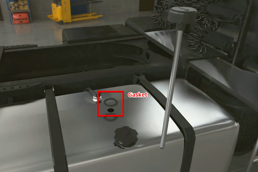
Install the sensor into the tank of the installed tube in the previously drilled hole ø 30-35 mm. Make sure '''the gasket is installed''' between the sensor and the tank. After this, screw the screws from the installation kit into the previously drilled ø 3mm holes.<gallery widths="700" heights="400"> | |||
File:Installing_the_sensor_inside_the_tank.png|'''<big>Installing the sensor inside the tank</big>''' | |||
File:Screwing_the_self-tapping_screws.png|'''<big>Screwing the self-tapping screws</big>''' | |||
</gallery> | </gallery>Proceed to tank calibration. This procedure will result in a "level-liters" (or "level-gallons") table that will allow your monitoring platform to convert the level values that the sensor provides into liters/gallons that are displayed in the monitoring platform reports. You can save the table to the sensor's memory so that the sensor immediately outputs volume values in liters/gallons. You do not need to enter a calibration table on the monitoring platform. The internal memory of the TD BLE sensor can hold up to 50 lines of the calibration table. The capacity of the table on the monitoring platform is usually larger.<blockquote>In addition, it is easier to change the table or correct errors in the calibration table when it is downloaded to the platform than if the table is stored in the sensor's memory</blockquote>In order to create such a table, you need to fill the tank by step by step adding fuel to the tank batch by batch and recording level-liter(/gallon) value pairs after each batch using the tank calibration menu in the application. | ||
Suppose you need to calibrate a 100 L tank in ten 10 L portions. | |||
[[ | To do this, you should connect the sensor, press the '''"Tank calibration"''' '''(2)''' button . But before that, in the '''"Settings" (3)''' menu , make sure that the filtering level is selected '''0 (4)'''. Filtration slows down the level calculation and can increase the tank calibration time.<gallery mode="nolines" widths="300" heights="600"> | ||
File:Settings_Tank_calibration.png|alt= | |||
File:Tank_calibration_filtration.png|alt= | |||
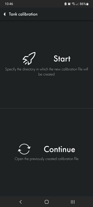
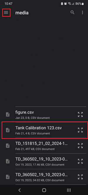
</gallery>Then, you can click '''Start''' to create a new table, or click Resume to select an existing table from your smartphone memory and continue working with it. If you click Resume, you will need to locate the table file on your Android device that you created/downloaded earlier. Select another folder using the '''Main Menu button (1)''' or using the drop-down menu '''(2)'''. Select the table and click on it '''(3)'''<gallery mode="nolines" widths="300" heights="700"> | |||
File:Tank_calibration_page.jpg|'''Start or Continue tank calibration''' | |||
File:Folder_search.png|'''Selecting the tank calibration table file for continuing tank calibration''' | |||
</gallery>If you click Start, you will also need to select the folder in which the table will be saved '''(2)''' and click the button to select it '''(3)''' | |||
[[File:Start_tank_calibration_folder.png|none|thumb|Selecting a folder and creating new calibration files]] | |||
Select the calibration type Manual '''(2).''' | |||
Mathematical calibration '''(1)''' is [[TD-BLE#Mathematical calibration|shown in this article.]] | |||
[[File:Selecting_type_of_tank_calibration_.png]] | |||
Then, you can select the '''Fill''' or '''Drain''' method '''(1, 2)'''. The '''Fill''' method is recommended as it is more accurate. | |||
If you select the Drain method, you cannot be sure what exact amount of fuel is in the tank and whether the tank is full or not | |||
Next, give the table file a name '''(3)''' and set the serving size '''(4)'''. | |||
'''ATTENTION!''' Serving volume is not the number of servings! This is the number of liters/gallons in each serving! In the example below, the tank supposedly contains 100 liters and this volume can be divided into 10 portions of 10 liters. If the volume of the tank was 300L and it needed to be packaged into 10 servings, the serving size would be 30 L. | |||
After this, press Continue '''(5)'''.<gallery widths="400" heights="600"> | |||
File:Tank_calibration_filling.png|'''Selection of tank calibration method, table name, portion size''' | |||
File:Tank_calibration_draining.png|'''Selection of drain tank calibration method, selection of fuel volume in the tank''' | |||
</gallery>After this, you will have a table in which the first line will have 0 liters and level 1. '''The Calibration''' mode will also be activated (available in firmware 1.3.3 and later). This means that the sensor starts measuring the level every 5 seconds instead of the usual 10 seconds. It will operate in this mode for the next 30 minutes.<gallery widths="400" heights="700"> | |||
File:Tank_calibration_first_line.jpg|'''First tank calibration line. 0 liters-gallons and level 1''' | |||
File:Tank_calibration_mode_notification.png|'''Tank calibration mode timer''' | |||
</gallery>If the timer ends before you finish calibrating the tank, you can restart it by saving the table '''(1, 2)''', and then, returning to the previous menu '''(3)''', click Continue and select the table file. This way you will restart the timer and can continue calibrating the tank in the accelerated level measurement mode. Once you select your file, you will be asked to confirm your previously selected method and serving size.<gallery widths="400" heights="700"> | |||
File:Saving_the_calibration_table_and_exiting_calibration.png|'''Saving the calibration table and exiting calibration''' | |||
File:Resuming_tank_calibration.jpg|'''Resuming tank calibration''' | |||
</gallery>The table is saved automatically after you click the '''+''' button. | |||
Next, you should add the first portion of fuel to the tank. Once the level changes '''(3)''' and is displayed as Stable '''(4)''', press the + button '''(1)'''. | |||
In this example, level '''(3)''' does not change because during the work on this manual we did not have fuel to carry out a real calibration of the tank. In your case, the level should change (if the fuel touches the tubes) and be '''Stable''' before you press the '''+''' button. | |||
[[ | The following line '''(2)''' will appear. The value in the Fuel column will increase according to the Step size '''(5)''' you specified when you created the table or when you last modified it '''(3)'''.<gallery widths="400" heights="700"> | ||
File:Adding_the_first_portion_to_the_tank.png|'''Adding the first portion to the tank''' | |||
File:Adding_a_tank_calibration_line.png|'''Adding a tank calibration line''' | |||
</gallery>You can also change any line by pressing and holding it for some time, after which a dialog box will appear. This way you can correct possible errors. | |||
[[File:Editing_a_tank_calibration_line.jpg|none|thumb|415x415px|'''Editing a tank calibration line''']] | |||
If you press a line and hold it and swipe left, it will be deleted. | |||
[[File:Tank_calibration_GIF.gif]] | |||
Then, add the next portion of fuel to the tank. Wait for the level to change and stabilize, then press the + button '''(1)'''. Continue this until the tank is full.<gallery widths="400" heights="700"> | |||
File:Adding_a_second_portion_to_the_tank.png|'''Adding a second portion to the tank''' | |||
File:Adding_a_tank_calibration_line.png|'''Adding a tank calibration line''' | |||
</gallery> | </gallery> | ||
== '''<big> | == '''<big>What to do if it is not possible to completely empty the tank?</big>''' == | ||
If you cannot completely empty the tank, you should somehow calculate the amount of fuel that is in the tank. After this, you can manually edit the table so that it looks like the example below. Or simply edit the table file before you upload it to the monitoring platform. | |||
Let's imagine that there are already 10 liters of fuel in the tank that cannot be removed, so when you place the sensor in the tank, it will immediately begin to show the level of 115, instead of 1.<gallery widths="400" heights="700"> | |||
File:Adding_the_first_portion_to_the_tank.png|'''10 liters of fuel in the tank that cannot be removed''' | |||
File:Calibration_table_with_10_liters_already_in_the_tank.jpg|'''Calibration table with 10 liters already in the tank''' | |||
</gallery> | </gallery>Next, you can add the next portion to the tank. The level value should change. If the level does not change, check the drain holes. They may be blocked by duct tape that you may have used while calibrating the sensor or by pieces of caulk. | ||
If this happens, the air trapped inside the tubes prevents the fuel from rising. | |||
== '''<big>Calibration of tanks with complex shape</big>''' == | |||
'''If the tank has various curves''' or other features, you should '''reduce the size of the portions and increase the number of portions''' as the fuel rises to the area with the bend or other shape feature. Once the difficult part has been completed, you can return to your original portion size. | |||
== | Let's imagine that you are calibrating a tank in 10-liter portions. The level rises to areas with complex shapes.<gallery mode="nolines" widths="350" heights="750"> | ||
File:Tank_calibration_complex_shape.png|alt= | |||
File:Changing_portion_size.png|alt= | |||
</gallery>You reduce the portion size from 10 liters to 5. And continue to add fuel portions until the difficult section is completed. | |||
[[File:Complex_shaped_tank_next_step.png|frameless|357x357px]] | |||
Once the fuel level is above the problem area, you can return to the original portion size of 10 liters. | |||
Once the tank is full, you should have a calibration chart that looks similar to the one shown below.<gallery widths="400" heights="500"> | |||
File:Tank_is_full.png|alt= | |||
File:Full_table.png|alt= | |||
</gallery> | </gallery> | ||
== '''<big> | == '''<big>What to do if the tank cannot be filled completely?</big>''' == | ||
If in your case the level does not reach the maximum range value of 1023 or 4095 due to the fact that the tank cannot be filled completely, do not worry. If your table ends up like the following example, even though the range selected is 1 - 1023, this is acceptable | |||
[[ | [[File:Tank_calibration_table_in_.csv_format.png|none|thumb|'''Tank calibration table in .csv format''']] | ||
== '''<big> | == '''<big>How many portions should I add?</big>''' == | ||
The total number of portions depends on the capacity of the tank. Below is a table with guidelines. | |||
{| class="wikitable" | {| class="wikitable" | ||
| colspan="3" | | | colspan="3" |Recommended number and portion size for calibrating the tank | ||
|- | |- | ||
| | |Tank volume | ||
| | |Number of portions | ||
| | |Volume of each portion | ||
(Tank Volume / Number of portions) | |||
( | |||
|- | |- | ||
|0-60 | |0-60 | ||
| Line 573: | Line 604: | ||
|20 | |20 | ||
|- | |- | ||
| | |Over a 1000 | ||
| colspan="2" | | | colspan="2" |As per your capabilities. The rule of thumb is that the larger the portions and smaller the volume, the more accurate the data will be | ||
|} | |} | ||
<blockquote><big> | <blockquote><big>The '''rule of thumb''': more portions means more accurate reports on the monitoring platform.</big></blockquote> | ||
= '''<big> | = '''<big>Filtration</big>''' = | ||
After the calibration table is completed, select the filtration level '''(2)''' in the '''Settings''' menu '''(1)''' and click Set parameters (3).<gallery mode="nolines" widths="350" heights="750"> | |||
File:Settings_Filtration.png|alt= | |||
File:Filtration_Selection.png|alt= | |||
</gallery> | </gallery>The following are recommendations for selecting a filter level depending on the type of vehicle: | ||
{| class="wikitable" | {| class="wikitable" | ||
|'''<big>0-1</big>''' | |'''<big>0-1</big>''' | ||
|'''<big> | |'''<big>Stationary objects or tanks</big>''' | ||
|- | |- | ||
|'''<big>2-4</big>''' | |'''<big>2-4</big>''' | ||
|'''<big> | |'''<big>Vehicles traveling on smooth paved roads</big>''' | ||
|- | |- | ||
|'''<big>5-7</big>''' | |'''<big>5-7</big>''' | ||
|'''<big> | |'''<big>Agricultural machinery</big>''' | ||
|- | |- | ||
|'''<big>8-10</big>''' | |'''<big>8-10</big>''' | ||
|'''<big> | |'''<big>Heavy quarry machinery</big>''' | ||
|} | |} | ||
These are general recommendations | |||
Basic rules: | |||
* | * The shorter the sensor (<30cm), the higher the filtration should be set | ||
* | * The closer the sensor is to one of the tank walls, the higher the filtration must be | ||
* | * The more rough the road, the higher the filtration should be | ||
Filtration reduces fuel level fluctuations that are caused by fuel splashing while driving. | |||
[[ | [[File:Filtration_effect.png|none|thumb|795x795px|'''<big>Before and after enabling filtering on the sensor</big>''']] | ||
= <big>'''Tank mounting'''</big> = | |||
The most common mounting method is self-tapping screws with a sealing washer. It is also possible to install on threaded crimp nuts, welded bushings and other structural elements. The sensor can be mounted on pre-prepared places using screws and bolts with strength class not less than 4.8. It is necessary to ensure tightness of the connection between the sensor body and the tank. For additional protection it is allowed to use automotive oil and gasoline resistant sealant. | |||
For plastic tanks rivets and bolts can be used. | |||
== <big>'''How hard to screw in self-tapping screws'''</big> == | |||
[[File:How_to_hard_to_tighten_the_screws.png|frameless|512x512px]] | |||
== <big>'''Saving a calibration table to the sensor memory'''</big> == | |||
If the calibration table is ready, you can '''save it to the sensor's memory so that the sensor will output volume values''' in liters/gallons. | |||
To activate this function, go to the '''Additional settings''' menu and press '''Conversion to liters''' .<blockquote>This function is not recommended for use if your platform supports the use of a billing table, because to edit the table on the sensor you will need to travel to the sensor, while the table on the platform can be edited remotely at any time.</blockquote>After that you can activate the conversion to liters or gallons and enter the conversion table manually or by uploading a ready table file. | |||
'''''If the table file is not selected - move it to another folder and try again, it is also desirable that the file name contains only digits''''' | |||
Activate '''Conversion to liters(1'''). | |||
To create the table manually, select Level'''(2''') or Liters'''(3''') - in this case it can be any volume unit, enter the value'''(4''') and click on the arrow'''(5'''). Then, click on the three dots icon'''(6''') and then click Save to sensor ('''7''').<gallery mode="nolines" widths="350" heights="550"> | |||
File:Recalculate_page.png|alt= | |||
File:Recalculate_page_settings.png|alt= | |||
</gallery>In order to import a table from the .csv file that you created earlier when calibrating the tank, click on the three dots icon (1), and then click Import from file (2). After that, find the desired file on your smartphone and click on it. | |||
Save the imported table to the sensor (3) | |||
[[File:Recalculate_page_settings_2.png|frameless]] | |||
= '''<big>Common issues and solutions</big>''' = | |||
== '''<big>Level does not change</big>''' == | |||
First of all, check if the '''conversion to liters has not been enabled'''. | |||
If you did this without saving the table to the sensor’s memory, the sensor will not be able to display either the level or volume in liters.<gallery widths="350" heights="600"> | |||
File:Recalculate_disabled.png|'''Recalculate in litres is disabled''' | |||
File:Recalculate_enabled.png|'''Recalculate in litres is enabled''' | |||
</gallery>Another possible reason could be that the sensor has not been properly calibrated and its CNT is below the Empty calibration value. In this case, recalibrate the sensor. | |||
Also, if you calibrated the sensor with fuel, it is possible that the sensor drain holes have remained closed and air trapped inside is preventing fuel from rising through the tubes. | |||
== '''<big>Level 7000</big>''' == | |||
Level 7000 is an error code Short circuit. This indicates that there is dirt, water, chips or other impurities in the tubes. All of these can be highly conductive, while the sensor is designed to work with dielectrics such as fuel. | |||
[[File:Level_7000.png|frameless]] | |||
You should clean the sensor tubes preferably by flushing them with the clean fuel and blowing them through the drain holes with compressed air. | |||
If this error occurred after the start of operation of the sensor, it means that most likely these impurities got into the sensor tubes from the tank and in this case it is also needed to ensure that the tank itself doesn't contain any contaminations. Clean the tank, if necessary. Note that a fuel level sensor installed outside a contaminated tank may function correctly, but the same sensor installed in such a tank may generate this error code. | |||
== '''<big>Level 6500</big>''' == | |||
This code may indicate that the tubes have lost contact. This error code may be generated immediately after cutting the tubes. In this case, simply calibrate the sensor. | |||
[[File:Level_6500.png|none|thumb|'''<big>Level 6500 and CNT below 10000</big>''']] | |||
If this does not help, check the CNT. If the CNT is below 10,000, it is very likely that the tubes are not in contact with the sensor board. | |||
Take a photo of the sensor head (the sensor serial number should be visible), its tubes (the correspondence or discrepancy of the tubes length should be clearly visible), take a screenshot of the main screen of the sensor and the Settings menu page in the application and send these data to tech support. | |||
== '''Connection losses, issues with coordinates, power supply issues''' == | |||
In case TD-Online goes offline for several days, it is necessary to check the messages the device sent before going offline or, if it has come back online, to check the messages sent from the black box. On Wialon platform such messages are marked with blue color. | |||
The dianostic parameters that need to be checked are: | |||
- '''SRN''' - in case it is higher than 30, there is an issue with the GPS connectivity; either the connection with satellites is poor in this area or there is an issue with the device's GPS module or its antenna | |||
- '''RSSI''' - Received Signal Strength Indicator - shows the quality of GSM signal reception; if the values you see are below 20 this means that either the local 2G/4G coverage is poor or there's an issue with the GSM modem or its antenna | |||
- '''msg_num''' - a cumulative counter of the messages sent; it can reset from time to time but if it happens too often then most likely there's an issue with the power supply the sensor is connected to | |||
[[File:TDOnline diagnostic parameters.png|980x980px]] | |||
=== Checking the device manually === | |||
If the TD-Online in question is offline for too long, it is necessary to check it manually. | |||
Once next to the vehicle: | |||
1) Before doing anything with the wiring, try and check if the device can be detected via Escort app (via Bluetooth) | |||
2) If it cannot be detected, there's something with: | |||
* a) the cable | |||
* b) the fuse | |||
* c) the device itself | |||
3) Try and connect the TD-Online to an alternative power supply of 12-24 V (using C200M2 RS485-USB converter is an option) and check if it can be detected via the app; if this works, run a continuity check on the cable and the fuse using a multimeter; replace either or both of them if they are damaged | |||
4) If the TD-Online is detected via the app, try and hard reset it; should it come back online on the platform, be sure to report that to the tech support team | |||
5) If the TD-Online is detected via the app but doesn't come back online on the platform no matter what you try, download the log from it and share the file with the tech support; the log file is saved in the same folder where you previously saved a tank calibraiton table; if you have never saved any tables before, be sure to create and save one (you need only a few lines in the table with whatever values)<gallery widths="250" heights="400"> | |||
File:2c18a2b1-b2ed-48f3-b9d7-9a3ae6f90d00.jpg|Find and connect the sensor | |||
File:Td online additional features.png|Go to Additional Features | |||
File:Td online additional features log and bb.png|1 - to download the log, 2 - to download the black box | |||
File:Td online log or bb selecting how much data to download.png|1 - select the number of days, 2 - hours, 3 - download the data for the number of days and/or hours you have selected; or 4 - download all the data stored | |||
File:8b579a96-aea4-419e-b0d2-59ffbd2b12a5.jpg|Download complete; the file is stored in the last folder you used to create and save a tank calibration table file in | |||
</gallery> | |||
= '''<big>Firmware update</big>''' = | |||
To update the firmware, be sure to donwload a .zip file onto your smartphone first. Do not unzip it! | |||
Then, once the sensor is connected, go to the '''Additional Features''' menu, enter the sensor's password (1) and initiate the '''FW update''' (2). You will have 30 seconds to quickly select the FW file and start the update. Otherwise, after 30 seconds, the sensor will restart and you will need to reconnect it. <gallery widths="350" heights="400"> | |||
File:Eng wiki tdo go to add feature fw upd.png|alt= | |||
File:Eng wiki tdo add feature fw upd.png|alt= | |||
</gallery>Next, tap on the FW file button, find the file in the folder where you previously saved it and select it. Then start the update and wait for it to finish.<gallery widths="250" heights="400"> | |||
File:Eng wiki tdo add feature fw upd select file.png|alt= | |||
File:Eng wiki tdo add feature fw upd find file.png|alt= | |||
File:Eng wiki tdo add feature fw upd start upd.png|alt= | |||
</gallery>Once the firmware update is over, you can reconnect the sensor. | |||
= '''<big>Connecting slave sensors (BLE and RS-485)</big>''' = | |||
TD-Online can function as a hub to which it is possible to connect up to '''8 slave sensors''' either via BLE or the RS-485 interface (in case of the wired sensors). | |||
== '''Pairing a BLE slave sensor''' == | |||
Go to the '''Additional settings''', once the TD-Online is connected to your smartphone via the app. Hit the '''"+"''' button. Then select '''Bluetooth''' (1), enter the sensor's name or its MAC address (2; both can be found on the sensor's head; the sensor's name is the model's letters TD, DU, TW, TH with a lower dash and the last 6 digits of the serial number f.e. TD_555666 or DU_222444) and tap on '''Connect'''. Or scan the slave sernsor's QR code (4).<gallery widths="300" heights="350"> | |||
File:Eng wiki tdo go to add settings.png|alt= | |||
File:Eng wiki tdo add settings connection of slave sensors.png|alt= | |||
File:Eng wiki tdo add settings start adding slave sensors.png|alt= | |||
File:Eng wiki tdo add settings adding slave sensors mac address or qr.png|alt= | |||
</gallery> | |||
== '''Connecting a wired slave sensor via the RS-485 interface''' == | |||
To connect a wired Escort-TD sensor as a slave device via the RS-485 interface, go to '''Additional settings''' menu, tap on the '''"+"''' button, then select the '''Wired''' option (1), enter the slave '''sensor's network address''' (2) and tap '''Connect'''. <gallery widths="300" heights="350"> | |||
File:Eng wiki tdo go to add settings.png|alt= | |||
File:Eng wiki tdo add settings connection of slave sensors.png|alt= | |||
File:Eng wiki tdo add settings start adding slave sensors.png|alt= | |||
File:Eng wiki tdo add settings adding slave sensor wired.png|alt= | |||
</gallery><blockquote>'''The salve's network address must be any number from 2 to 200. You can't use the network address 1 as it is already taken by the TD-Online itself.'''</blockquote>Before connecting the wired sensors to a TD-Online, be sure to connect them separately and change their network addresses via the PC configurator or the app. | |||
[[File:Eng wiki tdo add settings adding slave sensors wired slave sensor network address.png|863x863px]] | |||
If using a PC configurator, the network address can be modified via the '''General settings''' menu. | |||
[[File:Escort TD wired network address modification General settings.png|800x800px]] | |||
== '''Cheking the slave sensors' data''' == | |||
Once a slave sensor is connected, tap on it to see its readings.<gallery widths="250" heights="300"> | |||
File:Eng wiki tdo add settings adding slave sensors finished.png|alt= | |||
File:Eng wiki tdo add settings adding slave sensors wired slave sensor data check.png|alt= | |||
</gallery> | |||
== | == '''Slave sensors' parameters in messages''' == | ||
ULx – level or angle reading of 'Slave Sensor x' | |||
VBx – battery voltage reading of 'Slave Sensor x' | |||
UTx – temperature reading of 'Slave Sensor x' | |||
VVx – FW version of 'Slave Sensor x' | |||
UCx – CNT reading of 'Slave Sensor x' | |||
WMx – operating mode of 'Slave Sensor x' | |||
' | LMx – luminosity reading of 'Slave Sensor x' | ||
UROx – roll reading of 'Slave Sensor x' | |||
UPTx – pitch reading of 'Slave Sensor x' | |||
UHx – humidity reading of 'Slave Sensor x' | |||
UPx – pressure reading of 'Slave Sensor x' | |||
UWx – weight reading of 'Slave Sensor x' | |||
DIx – DIN state reading of 'Slave Sensor x' | |||
ZULx – coefficient reading of TDQ-BLE paired with 'Slave Sensor x' | |||
ZUTx – temperature reading of TDQ-BLE paired with 'Slave Sensor x' | |||
ZUCSx – status of TDQ-BLE paired with 'Slave Sensor x' | |||
UZx – CNT reading of TDQ-BLE paired with 'Slave Sensor x' | |||
= '''<big>Wiring</big>''' = | |||
[[File:TD Onlinewiring no slave.png|532x532px]] | |||
TD-Online with a slave sensor(s) | |||
[[File:TD-Online wiring with a slave sensor.png|864x864px]] | |||
= '''<big> | = '''<big>Useful links</big>''' = | ||
* '''<big>[https://www.fmeter.ru/download/_ftp/datchik-urovnja-topliva/eskort-td-online-sim/% | * '''<big>[https://www.fmeter.ru/download/_ftp/eng/datchik-urovnja-topliva/eskort-td-online-sim/Datasheet%20TD-online.pdf?v=160719173609 Technical data sheet of the device]</big>''' | ||
* '''<big>[https://www.fmeter.ru/download/# | * '''<big>[https://www.fmeter.ru/en/download/#tdonline Download materials]</big>''' | ||
Latest revision as of 16:27, 28 April 2026

Definition and Purpose of the Sensor
The TD-Online measuring device (sensor) determines the fill level of light petroleum products in tanks (storage containers). It is used in automotive and tractor equipment as a fuel level sensor and in industrial applications as a level sensor for various light petroleum products.
The sensor converts the level into a digital code and transmits the value to an external server. It also sends information about its location and speed to the external server.
More detailed technical specifications can be found in the device's technical datasheet.
Basic Terms, Definitions, and Specifications
Fuel Level Sensor (FLS) - a device designed to measure fuel level.
Serial number - a code consisting of a series of letters or numbers assigned to a product (sensor).
Sensor name - the sensor identifier among BLE devices, composed of the first two letters of the sensor model and the last six digits of the serial number; for example, TD_100100.
Advertising mode - a data transmission mode where the device broadcasts data packets at a set frequency regardless of the presence of a receiving device.
Connection mode - a data transmission mode where the transmitter waits for connection to a receiving device before starting data packet transmission.
GSM modem standard - 4G (backward compatible with 3G, 2G)
GSM module - Simcom
Data transfer protocol to server - Wialon IPS
Remote configuration - yes (under development)
Point generation frequency - adaptive mechanism
Fuel level measurement frequency - once per second
Bluetooth data transmission (Advertising) - once per second
Engine status tracking capability - yes (after calibration based on onboard voltage)
Deviation angle from calibrated horizon - yes (3-axis accelerometer; vehicle movement detection)
Roaming on/off - yes
Number of SIM cards - 1
SIM card size - nano
Multi-carrier SIM, multiSIM - Yes
Number of servers - 1
Support for wired (RS-485) and BLE slave sensors - under development (up to 7 sensors total)
BLE scanning frequency - continuous (similar to BA-BLE adapters)
Ability to store calibration table in sensor - yes (50 entries)
Black box capacity - 15,000 records
Single record size (with slave sensors) - up to 2 KB
SIM Card Installation
Before connecting and configuring the TD-Online (hereafter referred to as "Sensor", "TD-Online", or "TDO"), you must install a SIM card in the slot. To do this, unscrew the cover mounting screws and remove the cover.


Press your finger on the tray cover, slide it sideways and lift it up to open the SIM tray as shown in the photo below.

Insert the nano-SIM into the tray, aligning the cut corner of both the tray and SIM card. Close the tray cover, press it firmly with your finger, and slide it sideways (toward the corner with the SIM card's cutout) to lock it into the grooves..


ATTENTION! FILL THE WHOLE INNER SPACE OF THE SENSOR'S HEAD WITH LITHOL (LITHIUM GREASE) AFTER INSERTING THE SIM! THIS WILL PROTECT THE CIRCTUIT AGAINST ANY FOREIGN LIQUIDS FILTRERING IN INSIDE THE SENSOR!


Connecting the Sensor in the Configuration App
To configure the sensor, connect it to a power source or PC/laptop using either C200M or C200M2 converter (both Escort converter models can serve as power sources for the sensor).
- Launch the Escort Configurator application (available on AppStore, Play Store, AppGallery)
- Tap "Sensor Configuration"
- Swipe down on the screen to refresh - select TD-Online from the device list
- Choose the sensor from the list and either: Tap the sensor name (1) to view its Advertising packet (Android devices only), or tap the "Connect" button (2) directly


First connection - set a password; for subsequent connections - enter the password to gain access to sensor configuration.
Attention! Setting an access password for the sensor is mandatory; otherwise, any user of the application will be able to reconfigure the Sensor. To reset a lost password - contact Escort Group technical support.
To view the Sensor's current data - press Data.


Swipe down on the screen to view all sensor data, including its IMEI. To return to the previous menu, tap the arrow in the top left corner (1).


GSM Settings
To configure data transmission via the GSM modem, tap the "GPS/GSM Settings" button. Then proceed to the "GSM Network Setup" section (1). The arrow in the top left corner (2) returns you to the previous menu.


Fill in the "APN", "Username", and "Password" fields (1, 2, 3) with the settings provided by your mobile operator for the SIM card installed in the Sensor.
In the "PIN Code" field, enter the PIN code of the SIM card installed in the Sensor (if applicable) (4).
Enable or disable data transmission in roaming (5).
You can change the synchronization server if you know the address of an alternative server you require (6).
Enable or disable message bundling (7). If this option is disabled, each sensor record will be transmitted as a separate message.
After making any changes to the settings, press the "Apply" button (8).
The arrow in the top left corner (9) returns you to the previous menu.
Server Settings
To access server settings, tap the "GPS/GLONASS and GSM Setup" button, then select "Server Settings" (1). Use the arrow in the top left corner to return to the previous menu (2).


Fill in the fields "Server IP", "Port", and "Server access password" (1, 2, 3).
You can find the required data in the monitoring platform you use.
For example, when working with Wialon, you need to select the "Wialon IPS" option in the object settings. The platform will provide its own IP and port. These need to be entered in the sensor configuration.
The server access password must be the same in both the Sensor settings and the object settings on the monitoring platform.
Select the data transfer connection type - TCP or UDP (4); the choice depends on the requirements of your monitoring platform.
Enter the "Unique device ID" if required by your platform (5).
To save any changes to the settings, click Apply (6).
The arrow in the top left corner is for returning to the previous menu (7).
Data Transmission to Server
To configure the data transmission frequency to the server, tap the "GPS/GSM Settings" button, then go to the "Message Transmission Settings" section (1). The arrow in the top left corner returns you to the previous menu (2).


Specify the "Transmission Period" in seconds (1).
This is the standard data transmission interval during movement. For example, if you set it to 60 seconds, the Sensor will send data to the server every 60 seconds while in motion, regardless of whether one or more of the following events occur:
- Sudden acceleration (calculated by coordinates);
- Sharp turn (calculated by coordinates);
- Ignition turning on (by voltage in the onboard network);
The "Minimum Transmission Period" field (2). For example, if you set it to 10 seconds: in this case the sensor won't send data more frequently than once every 10 seconds, even if the above events occur more often than once every 10 seconds.
"Transmission Period Multiplier" (3) - this is the value by which the message transmission interval will increase if the Sensor detects a stop (according to its accelerometer readings).
For example, with a "Transmission Period" of 60 seconds and a "Transmission Period Multiplier" of 5, during parking (with ignition off) data will be transmitted once every 60×5=300 seconds, i.e. once every 5 minutes.
"Turn Angle Threshold" (4) - a threshold value in degrees, upon exceeding which the Sensor registers a sharp turn based on its accelerometer readings.
"Speed Threshold" (5) - a threshold value of speed calculated by the Sensor based on coordinate changes; if the speed changes abruptly by the specified value, the Sensor registers the event and generates an out-of-sequence message (but no more frequently than once per the minimum transmission period (2)).
After making changes to the settings, click Apply (6).
The arrow in the top left corner - to return to the previous menu (7).
General Parameters Transmitted by the Sensor
msg_num - sequential record number since startup (cumulative counter of the messages sent)
SNR - signal-to-noise ratio for GPS
RSSI (Received Signal Strength Indicator) - quality of the GSM signal reception
pwr - power supply voltage
temp - temperature
angle - tilt angle relative to horizontal
fl - fuel level
fp - fuel level counter (CNT)
flX - (fl0...fl7) - slave devices' fuel levels
ftX - (ft0...ft7) - slave devices' temperatures
fpX - (fp0...fp7) - slave devices' fuel level counters (CNT)
move - whether in motion
engine - whether engine is running
Sensor calibration

CNT. What happens when you calibrate a sensor?
After you have cut or extended the sensor tubes, you should calibrate it, that is, set the new Full and Empty calibration values. You can do this from the Settings menu on the sensor's main screen.

The sensor's raw data - current level or CNT - changes according to how much fuel is inside its tubes.
Then, CNT is compared with the values Empty and Full.
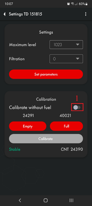
If the tubes are empty and “CNT (1) ≈ calibration value Empty (2)”, level 1 (3) will be displayed.


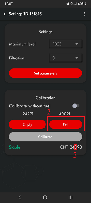
If the tubes are full and “CNT (1) ≈ calibration value Full (2)”, level 1023 or 4095 (3) will be displayed. Difference Between CNT and Calibration Values ("Empty" or "Full")


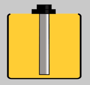
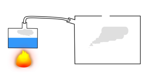
Thus, CNT should increase as the sensor tubes fill with fuel. It should change from a value close to the Empty calibration value to the Full calibration value.
![]()
During sensor calibration, the current CNT is stored as a Full calibration value (if you pressed the Full button) or as an Empty calibration value (if you pressed the Empty button). Calibration values may differ from the current CNT after recording. A difference of ±1000 values is acceptable.
How and why to calibrate sensors?
Initially, the sensor is calibrated to its original length. After you have cut or extended the tubes, you should recalibrate it. Set the new CNT values that the sensor has when its tubes are empty or filled with fuel.
Therefore you should:
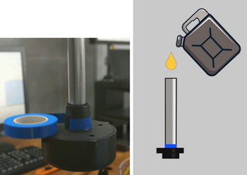
- Insert the plastic centralizer provided into the tubes


- Fill the tubes with fuel by covering the drain holes with electrical tape and turning the sensor upside down or immersing the sensor in fuel so that the fuel reaches the flange of the sensor (the drain holes are open). The first method is preferable
-
Closing the drain holes, rotating the sensor, and filling the tubes with fuel
-
Filling the tubes by immersing the sensor in fuel (drain holes open)

.png)
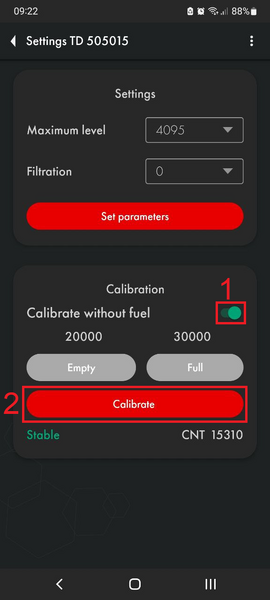
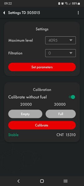
- Switch the "Calibration without fuel" slider to the inactive position (1) and press the Full button (2) after the level becomes Stable or the third digit from the end stops changing (for at least 2 minutes) (3)
-
Disable the option "Calibrate without fuel"
-
Click "Full" after the level has stabilized


- Then, drain the fuel from the tubes, wait 2-3 minutes, allowing the fuel to completely drain and the level to stabilize, and press "Empty"

![]()
Calibration without fuel
An alternative calibration method is calibration without fuel.
In this case, make sure that the sensor tubes are empty and there is no fuel in them, but the centralizer must be inserted into the tubes. Leave the "Calibrate without fuel" switch (1) active (green) and press "Calibrate" (2) . The values above the Empty and Full buttons will change automatically.
-
Calibration without fuel
-
Calibration values BEFORE calibration without fuel
-
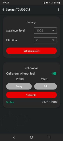
Calibration values after calibration without fuel


If you calibrate the sensor without fuel, the operating range may change slightly.
There are two measuring ranges:
- From 1 to 1023
- From 1 to 4095
Sensor does not sends level 0. If there is no fuel, level 1 is level sent.
The sensor itself does not know what fuel will be used, so when calibrating without fuel the "Empty" value is set based on the current (CNT), the "Full" value is set by a formula and, depending on the length of the tubes and the final fuel used, the range may change .
For example, when the tank is full, the sensor will show 3843 instead of 4095, or it is possible that when the tank is 98% full, the sensor will already display the value 4095.
If possible, we recommend calibration with fuel. If tank calibration is not planned or is impossible, then calibration with fuel is a mandatory procedure.
When and how to choose a range - 1023 or 4095?
The measuring range 1...1023 is generally recommended for sensors shorter than 500 mm. The measurement range 1...4095 is recommended in other cases.
To change the range, open the Settings menu and select one of two options from the "Maximum Level" drop-down menu (1). After this, click on the “Set parameters” button (2).


How to check if the calibration is correct?
The Empty calibration value must be at least 1.4 (after rounding) less than the Full calibration value.

Calibration of engine hours function
After installing TD-Online in the tank, connect it to the vehicle's onboard power supply.
Start the engine and bring it to operating condition. In the app, open the "Additional Settings" menu. Wait for 3-5 minutes, then press the "Calibrate" button in the "Engine On" section (1).
Then, turn off the engine. Wait for 3-5 minutes and press "Calibrate" in the "Engine Off" section (2).
The arrow in the top-left corner returns you to the previous menu (3).


Accelerometer Calibration
After installing TD-Online in the tank, connect it to the vehicle's onboard power supply. Ensure the vehicle is on a level surface.
Start the engine and bring it to operating condition. In the app, open the "Additional Settings" menu. Press "Calibrate" in the "Zero Angle Calibration" section (1).
The arrow in the top-left corner returns you to the previous menu (2).

Preparing the Tank and Sensor
Preparing the Tank
To prepare the tank you should:
- Empty the tank, clean and dry if necessary
- Remove fuel vapors and air from the tank (especially for a gasoline tank, but in the case of a diesel engine, this procedure should not be neglected, since gasoline could be added to the diesel); to do this, you can heat water to boiling point and direct the resulting steam into the tank or use carbon dioxide so that it displaces fuel vapors and air; ensure that any open flame sources are sufficiently far away from the fuel tank
- Find the geometric center of the tank and drill a hole in it using a ø3mm drill bit. Then, using a piece of stiff wire, examine the tank for the presence of partitions in it
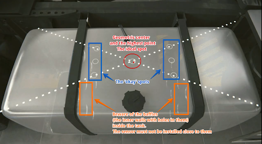
Choosing a location for installing the FLS 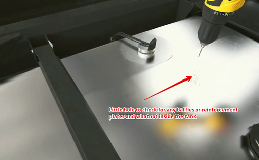
Drilling the tank and subsequent examination of the tank for the presence of partitions - If the space inside the tank in the selected location is free, drill a ø 35 mm hole using a bimetallic bit; When drilling, keep the bit tilted slightly to prevent the cut section from falling into the tank. Use a magnet to catch chips and prevent them from getting into the tank.
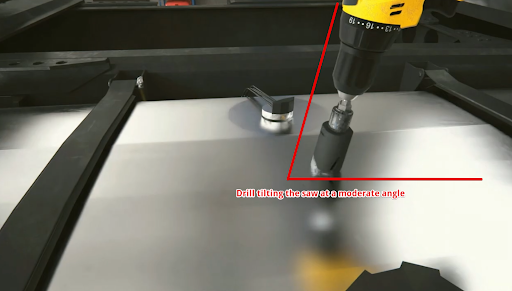
Drilling a hole at an angle 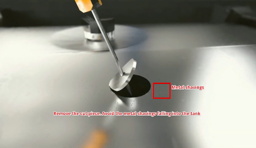
Removing a drilled disc - If it is impossible to install the sensor in the geometric center of the tank, try choosing another location as close as possible to the geometric center of the tank; this point should coincide with the place where the height of the tank is maximum. This way you reduce the risk and amplitude of level fluctuations associated with fuel movement while driving.


Why should the sensor be mounted in the geometric center of the tank?
The highest point must be chosen so that the sensor can measure the level of all the fuel inside the tank without any blind spots.
The fuel level readings from a sensor installed in the center of the tank will be least affected by movement and fuel overflow in the tank.
If it is not possible to install the sensor in the center of the tank, consider installing two sensors diagonally at two corners. When fuel flows to one side of the tank, the level on the corresponding sensor will rise, and on the opposite side, the level will correspondingly decrease, while the average level will remain unchanged.
Video example of the importance of installing the sensor at the geometric center of the tank.

Attention: Before starting the calibration, the vehicle/fuel tank must be positioned flat in relation to the horizon, i.e. on a level surface without a slope.
If the tank has an irregular geometric shape, the sensor must be installed at the maximum depth of the tank, closer to the geometric center.


When installation in the center is impossible - two or more FLS.
To increase accuracy and reduce level fluctuations, install two sensors in one tank. This solution is mainly used in tanks with a capacity of more than 600 liters and having a length of 1500 mm. Sensors must not be installed close to the walls of the tank.
Also, two or more sensors should be installed if it is not possible to install the sensor in the center of the tank and (or) the tank has an elongated shape, i.e. The length of the tank is significantly greater than its height.

Note. Installing a single sensor in an elongated tank will allow you to detect drains and refills. But increased level fluctuations while driving may not allow the monitoring platform to correctly read fuel consumption. Therefore, installing two sensors is preferable.
Installation locations in tanks of complex shapes
Saddle-Style Fuel Tanks
In this case, it is desirable to install two fuel level sensors in the deepest places along the geometric center of the depressions.


Cylindrical tank
In this case, the sensor must be installed in the geometric center of the tank.


Long cylindrical tank
In the case of elongated cylindrical tanks, to improve readings while driving, it is necessary to install two sensors at an equal distance from the geometric center of the tank.


Ladder shape tank
If there is a difference in height in the tank and there is no common bed, it may be necessary to install two fuel level sensors.


Ladder shape tank's tank calibration
When calibrating, it is necessary to create two tables, one for "FLS 1" and the second for "FLS 2"
Let's assume that the calibration step is 10 liters.
At the beginning of calibration, when the fuel is in the "Red Zone", the level changes will only occur on "FLS 2", so we directly add calibration steps of 10 liters to the table for "FLS 2".
When the fuel is in the "Yellow Zone" changes will occur on both "FLS 1" and "FLS 2", during this period we record changes in both tables with half a step, that is, we also fill in 10 liters, but we record 5 liters in the table of each sensor.
When the fuel is in the "Green Zone" the changes will only occur on "FLS 1" so we directly add calibration steps of 10 liters to the table for "FLS 1".
On the platform "FLS 1" and "FLS 2" are started as separate sensors with their own tables and then a third virtual sensor is created with the sum of liters for two sensors, an example of starting two FLS on the platform is shown in this instruction.

Preparing the sensor
Preparing the sensor tubes
Before calibrating the sensor, you should determine the future length of the measuring tubes in accordance with the height of the tank and cut or extend them. The length of the tubes should be calculated according to the following formula:
L = H - 15 mm,
where L - tubes length after changing the length
and
H - height of the tank at the installation point.
ATTENTION!!! The minimum length of the tubes should not be less than 15 cm (150 mm). Otherwise, it will most likely not be possible to obtain adequate graphics. The maximum length of the tubes can reach 6m.


Use a hacksaw to cut the tubes. When sawing, be careful not to damage the connection of the tubes to the circuit board inside the sensor head and to prevent metal shavings from falling into the tubes.

Avoid getting shavings inside the tubes - this may lead to a short circuit in the sensor; if this happens, blow the tubes with compressed air through the drainage holes under the sensor flange. Sand the edges of the tubes with sandpaper to remove any burrs or irregularities.
To extend sensor tubing, use a collet extension and an additional tube.

Inner nuts (yellow elements) are used to connect the inner tubes. Once they are installed and the studs are screwed into them, the tubes do not have to touch each other, but try to get them as close to each other as possible..

The outer coupling and the corresponding nuts must be securely tightened. The outer tubes should touch each other.

Watch this video on our YouTube channel to see the real-time connection.
Connection dimensions of the TD-Online of the former design

Connection dimensions of the TD-Online of the current design


Wiring diagram for sensor connection

Tank calibration
Once the length sensor has been adjusted to the height of the tank and the sensor has been calibrated, you need to install it in the tank.
Install the sensor into the tank of the installed tube in the previously drilled hole ø 30-35 mm. Make sure the gasket is installed between the sensor and the tank. After this, screw the screws from the installation kit into the previously drilled ø 3mm holes.
-
Installing the sensor inside the tank
-
Screwing the self-tapping screws


Proceed to tank calibration. This procedure will result in a "level-liters" (or "level-gallons") table that will allow your monitoring platform to convert the level values that the sensor provides into liters/gallons that are displayed in the monitoring platform reports. You can save the table to the sensor's memory so that the sensor immediately outputs volume values in liters/gallons. You do not need to enter a calibration table on the monitoring platform. The internal memory of the TD BLE sensor can hold up to 50 lines of the calibration table. The capacity of the table on the monitoring platform is usually larger.
In addition, it is easier to change the table or correct errors in the calibration table when it is downloaded to the platform than if the table is stored in the sensor's memory
In order to create such a table, you need to fill the tank by step by step adding fuel to the tank batch by batch and recording level-liter(/gallon) value pairs after each batch using the tank calibration menu in the application.
Suppose you need to calibrate a 100 L tank in ten 10 L portions.
To do this, you should connect the sensor, press the "Tank calibration" (2) button . But before that, in the "Settings" (3) menu , make sure that the filtering level is selected 0 (4). Filtration slows down the level calculation and can increase the tank calibration time.


Then, you can click Start to create a new table, or click Resume to select an existing table from your smartphone memory and continue working with it. If you click Resume, you will need to locate the table file on your Android device that you created/downloaded earlier. Select another folder using the Main Menu button (1) or using the drop-down menu (2). Select the table and click on it (3)
-
Start or Continue tank calibration
-
Selecting the tank calibration table file for continuing tank calibration


If you click Start, you will also need to select the folder in which the table will be saved (2) and click the button to select it (3)

Select the calibration type Manual (2).
Mathematical calibration (1) is shown in this article.

Then, you can select the Fill or Drain method (1, 2). The Fill method is recommended as it is more accurate.
If you select the Drain method, you cannot be sure what exact amount of fuel is in the tank and whether the tank is full or not
Next, give the table file a name (3) and set the serving size (4).
ATTENTION! Serving volume is not the number of servings! This is the number of liters/gallons in each serving! In the example below, the tank supposedly contains 100 liters and this volume can be divided into 10 portions of 10 liters. If the volume of the tank was 300L and it needed to be packaged into 10 servings, the serving size would be 30 L.
After this, press Continue (5).
-
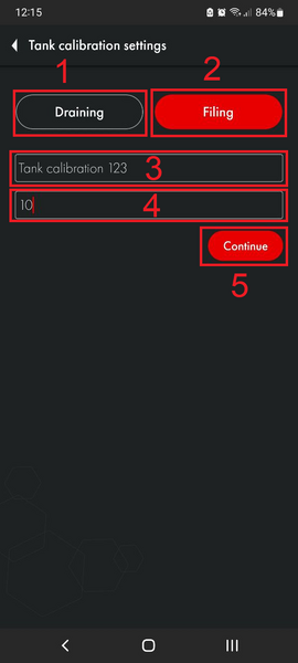
Selection of tank calibration method, table name, portion size
-
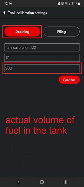
Selection of drain tank calibration method, selection of fuel volume in the tank


After this, you will have a table in which the first line will have 0 liters and level 1. The Calibration mode will also be activated (available in firmware 1.3.3 and later). This means that the sensor starts measuring the level every 5 seconds instead of the usual 10 seconds. It will operate in this mode for the next 30 minutes.
-
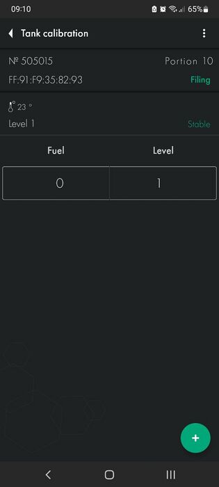
First tank calibration line. 0 liters-gallons and level 1
-
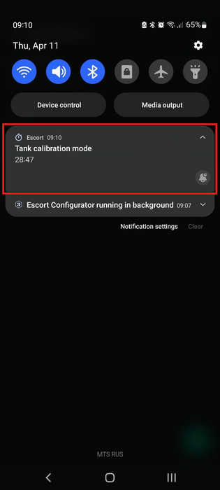
Tank calibration mode timer


If the timer ends before you finish calibrating the tank, you can restart it by saving the table (1, 2), and then, returning to the previous menu (3), click Continue and select the table file. This way you will restart the timer and can continue calibrating the tank in the accelerated level measurement mode. Once you select your file, you will be asked to confirm your previously selected method and serving size.
-

Saving the calibration table and exiting calibration
-
Resuming tank calibration


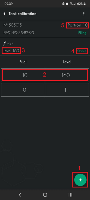
The table is saved automatically after you click the + button.
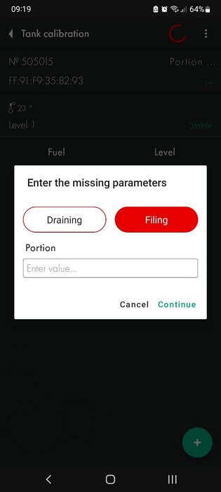
Next, you should add the first portion of fuel to the tank. Once the level changes (3) and is displayed as Stable (4), press the + button (1).
In this example, level (3) does not change because during the work on this manual we did not have fuel to carry out a real calibration of the tank. In your case, the level should change (if the fuel touches the tubes) and be Stable before you press the + button.
The following line (2) will appear. The value in the Fuel column will increase according to the Step size (5) you specified when you created the table or when you last modified it (3).
-

Adding the first portion to the tank
-
Adding a tank calibration line


You can also change any line by pressing and holding it for some time, after which a dialog box will appear. This way you can correct possible errors.

If you press a line and hold it and swipe left, it will be deleted.

Then, add the next portion of fuel to the tank. Wait for the level to change and stabilize, then press the + button (1). Continue this until the tank is full.
-
Adding a second portion to the tank
-
Adding a tank calibration line

What to do if it is not possible to completely empty the tank?
If you cannot completely empty the tank, you should somehow calculate the amount of fuel that is in the tank. After this, you can manually edit the table so that it looks like the example below. Or simply edit the table file before you upload it to the monitoring platform.
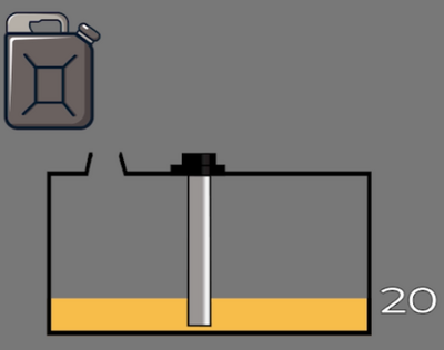
Let's imagine that there are already 10 liters of fuel in the tank that cannot be removed, so when you place the sensor in the tank, it will immediately begin to show the level of 115, instead of 1.
-
10 liters of fuel in the tank that cannot be removed
-

Calibration table with 10 liters already in the tank

Next, you can add the next portion to the tank. The level value should change. If the level does not change, check the drain holes. They may be blocked by duct tape that you may have used while calibrating the sensor or by pieces of caulk.
If this happens, the air trapped inside the tubes prevents the fuel from rising.
Calibration of tanks with complex shape
If the tank has various curves or other features, you should reduce the size of the portions and increase the number of portions as the fuel rises to the area with the bend or other shape feature. Once the difficult part has been completed, you can return to your original portion size.
Let's imagine that you are calibrating a tank in 10-liter portions. The level rises to areas with complex shapes.


You reduce the portion size from 10 liters to 5. And continue to add fuel portions until the difficult section is completed.

Once the fuel level is above the problem area, you can return to the original portion size of 10 liters.
Once the tank is full, you should have a calibration chart that looks similar to the one shown below.


What to do if the tank cannot be filled completely?
If in your case the level does not reach the maximum range value of 1023 or 4095 due to the fact that the tank cannot be filled completely, do not worry. If your table ends up like the following example, even though the range selected is 1 - 1023, this is acceptable

How many portions should I add?
The total number of portions depends on the capacity of the tank. Below is a table with guidelines.
| Recommended number and portion size for calibrating the tank | ||
| Tank volume | Number of portions | Volume of each portion
(Tank Volume / Number of portions) |
| 0-60 | 10-20 | 3-4 |
| 61-100 | 12-20 | 5 |
| 101-500 | 10-50 | 10 |
| 501-1000 | 20-50 | 20 |
| Over a 1000 | As per your capabilities. The rule of thumb is that the larger the portions and smaller the volume, the more accurate the data will be | |
The rule of thumb: more portions means more accurate reports on the monitoring platform.
Filtration
After the calibration table is completed, select the filtration level (2) in the Settings menu (1) and click Set parameters (3).


The following are recommendations for selecting a filter level depending on the type of vehicle:
| 0-1 | Stationary objects or tanks |
| 2-4 | Vehicles traveling on smooth paved roads |
| 5-7 | Agricultural machinery |
| 8-10 | Heavy quarry machinery |
These are general recommendations
Basic rules:
- The shorter the sensor (<30cm), the higher the filtration should be set
- The closer the sensor is to one of the tank walls, the higher the filtration must be
- The more rough the road, the higher the filtration should be
Filtration reduces fuel level fluctuations that are caused by fuel splashing while driving.

Tank mounting
The most common mounting method is self-tapping screws with a sealing washer. It is also possible to install on threaded crimp nuts, welded bushings and other structural elements. The sensor can be mounted on pre-prepared places using screws and bolts with strength class not less than 4.8. It is necessary to ensure tightness of the connection between the sensor body and the tank. For additional protection it is allowed to use automotive oil and gasoline resistant sealant.
For plastic tanks rivets and bolts can be used.
How hard to screw in self-tapping screws

Saving a calibration table to the sensor memory
If the calibration table is ready, you can save it to the sensor's memory so that the sensor will output volume values in liters/gallons.
To activate this function, go to the Additional settings menu and press Conversion to liters .
This function is not recommended for use if your platform supports the use of a billing table, because to edit the table on the sensor you will need to travel to the sensor, while the table on the platform can be edited remotely at any time.
After that you can activate the conversion to liters or gallons and enter the conversion table manually or by uploading a ready table file.
If the table file is not selected - move it to another folder and try again, it is also desirable that the file name contains only digits
Activate Conversion to liters(1).
To create the table manually, select Level(2) or Liters(3) - in this case it can be any volume unit, enter the value(4) and click on the arrow(5). Then, click on the three dots icon(6) and then click Save to sensor (7).


In order to import a table from the .csv file that you created earlier when calibrating the tank, click on the three dots icon (1), and then click Import from file (2). After that, find the desired file on your smartphone and click on it.
Save the imported table to the sensor (3)

Common issues and solutions
Level does not change
First of all, check if the conversion to liters has not been enabled.
If you did this without saving the table to the sensor’s memory, the sensor will not be able to display either the level or volume in liters.
-
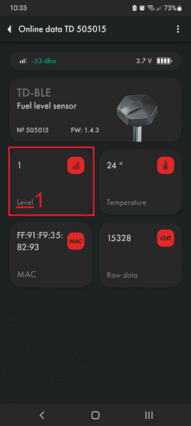
Recalculate in litres is disabled
-

Recalculate in litres is enabled


Another possible reason could be that the sensor has not been properly calibrated and its CNT is below the Empty calibration value. In this case, recalibrate the sensor.
Also, if you calibrated the sensor with fuel, it is possible that the sensor drain holes have remained closed and air trapped inside is preventing fuel from rising through the tubes.
Level 7000
Level 7000 is an error code Short circuit. This indicates that there is dirt, water, chips or other impurities in the tubes. All of these can be highly conductive, while the sensor is designed to work with dielectrics such as fuel.

You should clean the sensor tubes preferably by flushing them with the clean fuel and blowing them through the drain holes with compressed air.
If this error occurred after the start of operation of the sensor, it means that most likely these impurities got into the sensor tubes from the tank and in this case it is also needed to ensure that the tank itself doesn't contain any contaminations. Clean the tank, if necessary. Note that a fuel level sensor installed outside a contaminated tank may function correctly, but the same sensor installed in such a tank may generate this error code.
Level 6500
This code may indicate that the tubes have lost contact. This error code may be generated immediately after cutting the tubes. In this case, simply calibrate the sensor.

If this does not help, check the CNT. If the CNT is below 10,000, it is very likely that the tubes are not in contact with the sensor board.
Take a photo of the sensor head (the sensor serial number should be visible), its tubes (the correspondence or discrepancy of the tubes length should be clearly visible), take a screenshot of the main screen of the sensor and the Settings menu page in the application and send these data to tech support.
Connection losses, issues with coordinates, power supply issues
In case TD-Online goes offline for several days, it is necessary to check the messages the device sent before going offline or, if it has come back online, to check the messages sent from the black box. On Wialon platform such messages are marked with blue color.
The dianostic parameters that need to be checked are:
- SRN - in case it is higher than 30, there is an issue with the GPS connectivity; either the connection with satellites is poor in this area or there is an issue with the device's GPS module or its antenna
- RSSI - Received Signal Strength Indicator - shows the quality of GSM signal reception; if the values you see are below 20 this means that either the local 2G/4G coverage is poor or there's an issue with the GSM modem or its antenna
- msg_num - a cumulative counter of the messages sent; it can reset from time to time but if it happens too often then most likely there's an issue with the power supply the sensor is connected to

Checking the device manually
If the TD-Online in question is offline for too long, it is necessary to check it manually.
Once next to the vehicle:
1) Before doing anything with the wiring, try and check if the device can be detected via Escort app (via Bluetooth)
2) If it cannot be detected, there's something with:
- a) the cable
- b) the fuse
- c) the device itself
3) Try and connect the TD-Online to an alternative power supply of 12-24 V (using C200M2 RS485-USB converter is an option) and check if it can be detected via the app; if this works, run a continuity check on the cable and the fuse using a multimeter; replace either or both of them if they are damaged
4) If the TD-Online is detected via the app, try and hard reset it; should it come back online on the platform, be sure to report that to the tech support team
5) If the TD-Online is detected via the app but doesn't come back online on the platform no matter what you try, download the log from it and share the file with the tech support; the log file is saved in the same folder where you previously saved a tank calibraiton table; if you have never saved any tables before, be sure to create and save one (you need only a few lines in the table with whatever values)
-
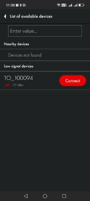
Find and connect the sensor
-
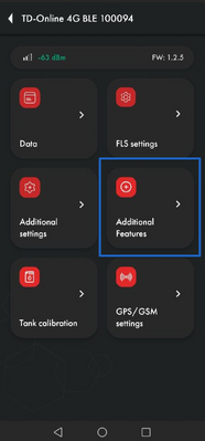
Go to Additional Features
-

1 - to download the log, 2 - to download the black box
-
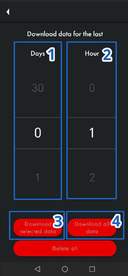
1 - select the number of days, 2 - hours, 3 - download the data for the number of days and/or hours you have selected; or 4 - download all the data stored
-
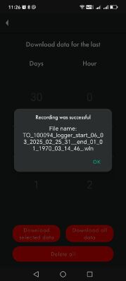
Download complete; the file is stored in the last folder you used to create and save a tank calibration table file in


Firmware update
To update the firmware, be sure to donwload a .zip file onto your smartphone first. Do not unzip it!
Then, once the sensor is connected, go to the Additional Features menu, enter the sensor's password (1) and initiate the FW update (2). You will have 30 seconds to quickly select the FW file and start the update. Otherwise, after 30 seconds, the sensor will restart and you will need to reconnect it.


Next, tap on the FW file button, find the file in the folder where you previously saved it and select it. Then start the update and wait for it to finish.


Once the firmware update is over, you can reconnect the sensor.
Connecting slave sensors (BLE and RS-485)
TD-Online can function as a hub to which it is possible to connect up to 8 slave sensors either via BLE or the RS-485 interface (in case of the wired sensors).
Pairing a BLE slave sensor
Go to the Additional settings, once the TD-Online is connected to your smartphone via the app. Hit the "+" button. Then select Bluetooth (1), enter the sensor's name or its MAC address (2; both can be found on the sensor's head; the sensor's name is the model's letters TD, DU, TW, TH with a lower dash and the last 6 digits of the serial number f.e. TD_555666 or DU_222444) and tap on Connect. Or scan the slave sernsor's QR code (4).


Connecting a wired slave sensor via the RS-485 interface
To connect a wired Escort-TD sensor as a slave device via the RS-485 interface, go to Additional settings menu, tap on the "+" button, then select the Wired option (1), enter the slave sensor's network address (2) and tap Connect.

The salve's network address must be any number from 2 to 200. You can't use the network address 1 as it is already taken by the TD-Online itself.
Before connecting the wired sensors to a TD-Online, be sure to connect them separately and change their network addresses via the PC configurator or the app.

If using a PC configurator, the network address can be modified via the General settings menu.

Cheking the slave sensors' data
Once a slave sensor is connected, tap on it to see its readings.


Slave sensors' parameters in messages
ULx – level or angle reading of 'Slave Sensor x'
VBx – battery voltage reading of 'Slave Sensor x'
UTx – temperature reading of 'Slave Sensor x'
VVx – FW version of 'Slave Sensor x'
UCx – CNT reading of 'Slave Sensor x'
WMx – operating mode of 'Slave Sensor x'
LMx – luminosity reading of 'Slave Sensor x'
UROx – roll reading of 'Slave Sensor x'
UPTx – pitch reading of 'Slave Sensor x'
UHx – humidity reading of 'Slave Sensor x'
UPx – pressure reading of 'Slave Sensor x'
UWx – weight reading of 'Slave Sensor x'
DIx – DIN state reading of 'Slave Sensor x'
ZULx – coefficient reading of TDQ-BLE paired with 'Slave Sensor x'
ZUTx – temperature reading of TDQ-BLE paired with 'Slave Sensor x'
ZUCSx – status of TDQ-BLE paired with 'Slave Sensor x'
UZx – CNT reading of TDQ-BLE paired with 'Slave Sensor x'
Wiring

TD-Online with a slave sensor(s)
