
ALS: Difference between revisions
(Begining of doing da choppa) |
|||
| (14 intermediate revisions by 2 users not shown) | |||
| Line 1: | Line 1: | ||
= '''<big>Definition and purpose of the sensor</big>''' = | = '''<big>Definition and purpose of the sensor</big>''' = | ||
[[ | [[RU:ALS| Русская версия]] | ||
[[File:Current design of ALS.jpg|thumb|[https://wikiru.fmeter.ru/images/thumb/8/8d/%D0%A2%D0%B5%D0%BA%D1%83%D1%89%D0%B8%D0%B9_%D0%B4%D0%B8%D0%B7%D0%B0%D0%B9%D0%BD_ALS.jpg/723px-%D0%A2%D0%B5%D0%BA%D1%83%D1%89%D0%B8%D0%B9_%D0%B4%D0%B8%D0%B7%D0%B0%D0%B9%D0%BD_ALS.jpg?20241218111713 '''<big>Current design of ALS</big>''']]] | |||
Escort's high-precision water level sensors ("WLS" or "ALS", also referred to as "gauges" or "sensors") are designed to determine the fill level of water in containers, tanks, and storage vessels. The ALS gauge is used in specialized equipment as a water level indicator and in industry as a level sensor for liquids with properties similar to water. The measurement principle of Escort's WLS is capacitive, relying on the dielectric permittivity of the medium; in this case, it measures the level of non-aggressive liquids such as water, aqueous solutions, liquid fertilizers, etc. Materials in contact with the measured liquid include aluminum alloy (AD-31) and polyacetal (PA-6). | Escort's high-precision water level sensors ("WLS" or "ALS", also referred to as "gauges" or "sensors") are designed to determine the fill level of water in containers, tanks, and storage vessels. The ALS gauge is used in specialized equipment as a water level indicator and in industry as a level sensor for liquids with properties similar to water. The measurement principle of Escort's WLS is capacitive, relying on the dielectric permittivity of the medium; in this case, it measures the level of non-aggressive liquids such as water, aqueous solutions, liquid fertilizers, etc. Materials in contact with the measured liquid include aluminum alloy (AD-31) and polyacetal (PA-6). | ||
''Note:'' The ALS sensor is not intended for use with liquid food products, such as milk, juices, fermented dairy products, etc., as it is not certified for these applications. | ''Note:'' The ALS sensor is not intended for use with liquid food products, such as milk, juices, fermented dairy products, etc., as it is not certified for these applications. | ||
More detailed technical characteristics are presented in the [https://www.fmeter.ru/download/_ftp/water-level-sensor/ | More detailed technical characteristics are presented in the [https://www.fmeter.ru/download/_ftp/eng/water-level-sensor/Datasheet%20Escort%20ALS.pdf?v=220225205325#page=21 technical data sheet of the device] | ||
= <big>'''Basic terms and concepts'''</big> = | = <big>'''Basic terms and concepts'''</big> = | ||
| Line 37: | Line 38: | ||
'''''Navigation terminal''''' - the main element of the system for monitoring the operation of transportation carried out by means of satellite communication. Without it, it is impossible to control transportation, to determine the coordinates of the vehicle location. It collects information from sensors and on-board system of the vehicle, and then transmits it to the device/server, which belong to the controlling specialist. | '''''Navigation terminal''''' - the main element of the system for monitoring the operation of transportation carried out by means of satellite communication. Without it, it is impossible to control transportation, to determine the coordinates of the vehicle location. It collects information from sensors and on-board system of the vehicle, and then transmits it to the device/server, which belong to the controlling specialist. | ||
= '''<big> | = '''<big>Preparation</big>''' = | ||
'''Why Should the Sensor Be Installed at the Geometric Center of a Mobile Tank?''' | |||
The highest point of the tank should be selected to ensure the sensor can measure the entire liquid level within the tank without any blind spots. | |||
The liquid level readings from a sensor installed at the center of the tank will be least affected by movement and sloshing of the liquid inside the tank. | |||
If it is not possible to install the sensor at the center of the tank, consider the option of installing two sensors diagonally at opposite corners. When liquid shifts towards one side of the tank, the corresponding sensor will show an increase in level, while the opposite sensor will show a decrease. This way, the average liquid level will remain unchanged. | |||
'''Video Example:''' | |||
= | [https://youtu.be/3psA2ACmw7w?si=zQ7n_N6h0HseNdfF A video demonstrating the importance of sensor installation at the geometric center of the tank, using a fuel tank as an example.] | ||
<blockquote>'''Attention:''' Before starting the calibration, the vehicle/tank must be positioned level with respect to the horizon, i.e., on a flat surface without any incline.</blockquote>If the tank has an irregular shape, the sensor should be installed at the point of maximum depth, as close to the geometric center as possible. | |||
[[File:The_sensor_is_installed_in_the_highest_place_of_the_tank.png|none|thumb|874x874px|'''<big>The sensor is installed in the highest place of the tank</big>''']] | |||
[[File:Ladder_tank.png|frameless|470x470px]] | |||
[[File:Ladder_tank_I.png|frameless|451x451px]] | |||
When installation at the center is not possible – use two or more sensors. | |||
To increase accuracy and reduce level fluctuations, two sensors are installed in one tank. This solution is primarily used for tanks with a capacity of more than 600 liters and a length of at least 1500 mm. Sensors should not be installed directly against the tank walls. | |||
Additionally, two or more sensors should be installed if it is not possible to position a sensor at the center of the tank and/or if the tank has an elongated shape, meaning the length of the tank is significantly greater than its height. | |||
[[File:Two_sensors_installed_diagonally.png|none|thumb|885x885px|'''<big>Two sensors installed diagonally</big>''']] | |||
'''Note:''' Installing a single sensor in an elongated tank will allow for detecting draining and filling. However, increased level fluctuations during movement may prevent the monitoring platform from accurately calculating the liquid consumption. Therefore, installing two sensors is preferred. | |||
== '''<big><u>Installation locations in tanks of complex shapes</u></big>''' == | |||
=== '''<big>Saddle-Style Fuel Tanks</big>''' === | |||
In this case, it is desirable to install two fuel level sensors in the deepest places along the geometric center of the depressions | |||
=== | === [[File:Saddle_shape.png|frameless|749x749px]] === | ||
[[File:Saddle_shape_top_view.png|frameless|749x749px]] | |||
[[ | [[File:Saddle_shape_side_view.png|frameless|749x749px]] | ||
=== '''<big>Cylindrical tank</big>''' === | |||
In this case, the sensor must be installed in the geometric center of the tank. | |||
[[File:Cylindrical_tank.png|frameless|750x750px]] | |||
[[File:Cylindrical_tank_top_view.png|frameless|750x750px]] | |||
[[File:Cylindrical_tank_inside_view.png|frameless|750x750px]] | |||
==== '''<big>Long cylindrical tank</big>''' ==== | |||
In the case of elongated cylindrical tanks, to improve readings while driving, it is necessary to install two sensors at an equal distance from the geometric center of the tank. | |||
[[ | [[File:Cylindrical_tank_long.png|frameless|750x750px]] | ||
[[File:Cylindrical_tank_long_inside_view.png|frameless|750x750px]] | |||
=== '''<big> | ==== '''<big>Ladder shape tank</big>''' ==== | ||
If there is a difference in height in the tank and there is no common bed, it may be necessary to install two water level sensors. | |||
[[File:Ladder_2_tank.png|frameless|782x782px]] | |||
[[File:Ladder_2_tank_inside_view.png|frameless|750x750px]] | |||
===== '''<big>Ladder shape tank's tank calibration</big>''' ===== | |||
During calibration, two tables need to be created: one for "Sensor 1" (ДУВ 1) and another for "Sensor 2" (ДУВ 2). | |||
Let's assume the calibration step is 10 liters. | |||
At the beginning of the calibration, when the liquid is in the "Red Zone," level changes will only occur on "Sensor 2," so we directly add the calibration steps of 10 liters to the table for "Sensor 2." | |||
When the liquid is in the "Yellow Zone," changes will occur on both "Sensor 1" and "Sensor 2." In this interval, we record changes in both tables with half-step increments. This means we add 10 liters, but in each sensor's table, we record 5 liters. | |||
When the liquid is in the "Green Zone," changes will occur only on "Sensor 1," so we directly add the calibration steps of 10 liters to the table for "Sensor 1." | |||
On the platform, "Sensor 1" and "Sensor 2" are configured as separate sensors with their own tables, and then a third virtual sensor is created, which sums the liters from both sensors. An example of configuring two sensors on the platform is shown. [https://docs.google.com/document/d/1nZHXENAhi-Do6VU2j5PE9KCO3n76H2fw-wBG70zncXg/edit?usp=sharing in this instruction..] | |||
[[File:ALS example1.png|frameless|680x680px]] | |||
== '''<big>Preparing the sensor</big>''' == | |||
=== '''<big>Preparing the sensor tubes</big>''' === | |||
Before calibrating the sensor, you should '''determine the future length''' of the measuring tubes in accordance with the height of the tank and '''cut or extend them'''. The length of the tubes should be calculated according to the following formula: | |||
'''L = H - 15 mm,''' | |||
where L - tubes length after changing the length | |||
and | |||
H - height of the tank at the installation point.<blockquote>'''<big>ATTENTION!!!</big>''' The ALS sensor is available with tube lengths of 950mm, 1450mm, 1950mm, and 2450mm.</blockquote> | |||
Use a hacksaw to cut the tubes . Be careful during the cutting process to avoid damaging the connection between the tubes and the PCB inside the sensor head, as well as the insulating material of the inner tube. | |||
'''After cutting the sensor tubes, use the special insulating heat shrink cap included with the sensor for insulating the inner tube. Use a heat gun or any other heating element to shrink the cap properly.''' | |||
Example: | |||
'''Take this plastic insulation cap''' | |||
[[ | [[File:Photo 2022-10-24 14-24-42.jpg|990x990px]] | ||
'''Cover the inner tube with this cap''' | |||
[[File:Photo 2022-10-24 14-24-42 (2).jpg|993x993px]] | |||
'''Press down on cover cap''' | |||
[[File:Photo 2022-10-24 14-19-54.jpg|992x992px]] | |||
'''<big> | '''Use hot air gun to finish the insultion''' | ||
[[File:Https s3.eu-central-1.wasabisys.comincoming-chat-api20221024861320276a824-1f9f-4c3c-a37c-3a1a00e28910.jpg|1000x1000px]] | |||
The extension of the water level sensor tubes is not allowed due to the design features of the inner tube. | |||
== '''<big>Connection dimensions</big>''' == | |||
[[File:Dimenstions_TD_150.png|none|thumb|702x702px|'''<big>Connection dimensions of the wired FLS</big>''']] | |||
= '''<big>Connection to the sensor, setup, calibration and calibration via [https://www.fmeter.ru/download/_ftp/all/dut/FLS_Configurator.zip?v=210521143455 the configurator on a PC]</big>''' = | |||
== '''<big>Installation of the configurator and connection to the sensor</big>''' == | |||
The sensor can be configured using [https://www.fmeter.ru/download/_ftp/all/dut/FLS_Configurator.zip?v=210521143455 '''<big>the configurator on a PC</big>'''] (From here onwards- "'''configurator'''"). | |||
'''Connect the sensor to the USB-RS-485 converter using a 6-pin MOLEX connector''' or using cable clamps if a cable route is connected to the sensor. Orange wire is line A of the RS-485 sensor interface, white wire is line B of the RS-485 sensor interface, black wire is GND, red is PWR. | |||
[[File:Sensor_connected_via_MOLEX.png|none|thumb|731x731px|'''<big>Sensor connected via MOLEX</big>''']] | |||
[[File:Sensor_connected_via_cables_and_cable_clamps.png|none|thumb|731x731px|'''<big>Sensor connected via cables and cable clamps</big>''']] | |||
We recommend using our Escort C200M/C200M2 USB-RS-485 converter, since we cannot guarantee 100% compatibility of our devices with converters from other brands. | |||
When working with a laptop, we recommend connecting it to the power supply and/or connecting an additional USB cable to the ADD connector of the PWR C200M. Otherwise, there may not be enough power to operate the sensor and transmitter. | |||
Along with installing the configurator 1.0.2.38, the drivers for the C200M will be installed automatically. | |||
If you use C200M2 on Windows 10 and 11 operating systems, drivers should be installed automatically from Windows Update, on the Windows 7 operating system and below, you may need to [https://windowsreport.com/driver-signature-enforcement-windows-10/ disable the electronic signature of drivers] and manually install [https://www.fmeter.ru/download/_ftp/eng/escort_c-200m/Escort%20driver%20C-200M2.zip?v=050623134319 drivers for the С200M2]. | |||
If the driver was installed correctly, then after connecting the converter to your PC/laptop, you will see the STMicroelectronics Virtual COM Port ('''1''')(C200M) or USB-SERIAL CH341A ('''2''')(C200M2) device in the COM and LPT ports section of the Windows device manager " to enter this menu, press '''win+r''' and enter '''devmgmt.msc''' and press '''OK''' ('''3''') and then expand the com ports submenu ('''4''')" | |||
The com port number displayed in this menu is also needed to connect the sensor. | |||
[[File:Com_ports_connected.png|frameless|796x796px]] | |||
After connecting the converter, sensor to it and checking the installation of drivers by checking the com port number of the converter, you need to open the configurator, select the desired com port which we could find in the device manager ('''1''') and press the '''FLS''' button ('''2'''). | |||
[[File:Com_ports_selection.png|frameless|657x657px]]<blockquote>The connection to the FLS should be made '''within 15 seconds after the sensor has been connected''' to power, if the sensor operating mode has been changed from RS-485 to any other. </blockquote>After connecting the sensor you should see this menu: | |||
[[File:Main_page_PC_configurator.png|frameless|751x751px]] | |||
#Sensor serial number | |||
# Sensor firmware version (FW) | |||
# Sensor temperature | |||
# Current sensor level | |||
# Current CNT level (raw level value) of the sensor | |||
# LLS network addresses connected to this converter (if there is more than one address in this list, it means either more than one sensor is connected to the line at the same time or there is interference on the line, in this case it is necessary to check the connection to the ALS for the presence of other conflicting devices and it is necessary to close other programs using the com ports for example tracker configurator) | |||
# Network address of the polled sensor (This address is used when connecting in RS485 mode) | |||
# Current sensor operating mode | |||
# Current range of output values (1-1023 or 1-4095) | |||
# Current filtration type and degree | |||
# Connected sensor model | |||
== '''<big>Sensor calibration</big>''' == | |||
[[File:FLS_calibration_PC.gif|frameless|647x647px]] | |||
After you have lengthened or shortened the sensor tubes, you need to carry out the sensor calibration procedure. | |||
To do this you need: | |||
* Go to menu '''"Sensor calibration"''' | |||
[[File:TD_150_calibration.png|frameless|734x734px]] | |||
* '''IMPORTANT! DO NOT INVERT THE SENSOR OR INTRODUCE LIQUID INTO THE INTERNAL TUBING IN A MANNER ANALOGOUS TO FUEL SENSORS. CALIBRATE THE SENSOR EXCLUSIVELY BY SUBMERGING THE TURBOC INTO A RESERVOIR CONTAINING THE FLUID IN WHICH THE SENSOR WILL BE OPERATED.''' | |||
*The water level sensor is designed based on a fuel sensor platform; therefore, the calibration menu will display the label "Calibration without fuel." | |||
*Wait for the CNT level to stabilize ('''1''') | |||
* Deselect the '''"Calibration without fuel'''" slider ('''2''') | |||
* Click '''"Full"''' ('''3''') | |||
* The value '''"Full"''' ('''4''') should change to a value close to the value of the current CNT ('''1'''), but not equal to it, since this value is set according to the temperature compensation of the sensor | |||
[[File:Wired_calibration.png|frameless|366x366px]] | |||
*Empty the pipes of fuel, leave the centralizer in the pipes | |||
* Wait for CNT to stabilize (1) | |||
* Click '''"Empty"''' ('''2''') | |||
* The value '''"Empty"''' ('''3''') should change to a value close to the value of the current CNT ('''1'''), but not equal to it, since this value is set according to the temperature compensation of the sensor | |||
* Click '''"OK"''' | |||
[[File:PC_Empty_calibration.png|frameless|366x366px]] | |||
*The sensor level should display as 1, the sensor calibration process is complete. Thus, CNT should increase as the sensor tubes fill with fuel. It should change from a value close to the Empty calibration value to the Full calibration value. | |||
'''<big>WARNING! For the ALS sensor, it is strongly advised to avoid using the automatic dry calibration function (formally labeled as "Calibration without fuel").</big>''' | |||
== '''<big>Setting the calibration value Full and Empty manually</big>''' == | |||
We do not recommend using this functionality, but you can set the Full and Empty calibration values manually to save time when you are using sensors of the same length in the same tanks.<blockquote>'''<big>Attention!!! Setting calibration values manually will most likely increase the sensor error! We do not recommend doing this!</big>'''</blockquote>To do this, enter the Full and Empty calibration values of the previously calibrated sensor into the appropriate fields in the configurator. | |||
[[File:Wired_advanced_menu.png|frameless|733x733px]] | |||
[[File:Wired_advanced_menu_page.png|frameless|669x669px]] | |||
[[File:Wired_manual_Empty-Full.png|frameless|667x667px]] | |||
== '''<big>Setting the mode, range and network address</big>''' == | |||
=== '''<big>Setting the mode</big>''' === | |||
In the main menu, you can change the operating mode of the sensor. The name of the mode coincides with the interface that is used to physically connect the sensor to the GPS terminal | |||
Select the mode you need('''1''') and click '''“Save parameters to device”'''('''2''') | |||
[[File:Wire_mode_settings.png|frameless|572x572px]] | |||
- '''Passive RS485''' should be selected when you plan to connect to line A and B of the terminal's RS-485 interface. The terminal must have the function of polling sensors, for example, requesting information from them. The terminal must be able to interrogate sensors in accordance with the '''LLS protocol'''. | |||
- '''Frequency mode''' is used when connecting to a GPS terminal to inputs that can receive and read signals in the range '''300 Hz … 1323 Hz''' or '''300 Hz … 4395 Hz'''. | |||
- '''Active RS485''' mode should be used if the terminal has an RS-485 connection interface, but cannot independently poll the sensor, for example, request information from it; the sensor will send its readings independently every 2 seconds.<blockquote>'''<big>Note: The analog output of the ALS is always active on the green wire in the 0.2-9V range, there is no need to turn it on separately</big>'''</blockquote> | |||
=== '''<big>Setting the range</big>''' === | |||
If you are configuring the sensor to operate in RS-485, Active RS-485, or Frequency modes, you can select the range '''1-1023 or 1-4095''' ('''1''') . In frequency mode, the range will be from '''300Hz to 1323Hz or 300Hz to 4395Hz'''. | |||
After changing the range, click “'''Save the parameters to device'''” ('''2'''). | |||
[[File:Wire_range_settings.png|frameless|561x561px]] | |||
'''The range 1-1023''' is most often used for sensors that are '''shorter than 1 meter'''. However, if we are talking about a stationary tank, the height of which is small, but the length and width are more than 2-3 m, it is better to choose the range 1-4095. | |||
=== '''<big>Setting the network address</big>''' === | |||
The default network address of the sensor is 1; if more than one unit is installed or other ALS devices are added, the network address on the sensor may need to be changed. The network address of each sensor must also be specified in the settings of the receiving device (navigation terminal).<blockquote>'''<big>Attention!!! There cannot be two devices with the same network address on the same line; this will cause a conflict.</big>'''</blockquote>To change the network address, enter a new address in the range '''0-255''' in the '''“Change network address”''' field ('''1''') and click '''“Save the parameters to device”''' ('''2'''), after which the configurator should switch to the new sensor address and display the new sensor address in the field '''"Available units"''' ('''3''') and '''"Poll network address"''' ('''4'''). | |||
[[File:Wired_before_changing_Network_address.png|none|thumb|611x611px|'''<big>Before changing network address</big>''']] | |||
[[File:After_changing_network_address.png|none|thumb|614x614px|'''<big>After changing network address</big>''']] | |||
== '''<big>Tank calibration</big>''' == | |||
'''The process is carried out similarly to the calibration procedure used with fuel sensors. For example, when using a sensor based on the''' [[TD-150]] | |||
== '''<big>Setting and removing a password</big>''' == | |||
If necessary, you can set a password on the sensor to change settings. | |||
To do this: | |||
* Click on the '''"Service"''' button ('''1''') and then '''"Security"''' ('''2''') | |||
[[File:Wired_security_menu.png|frameless|780x780px]] | |||
* In the menu that opens, you can enter a password consisting of numbers and then click set password. '''Also note that the password cannot start with 0.''' [[File:Password_menu_wired.jpg|frameless|777x777px]] | |||
*After successfully setting the password, a red lock should appear next to the FLS icon [[File:PC_password_set_menu.png|frameless|781x781px]] | |||
<blockquote>'''<big>PLEASE NOTE THAT THE PASSWORD RESET PROCEDURE CAN BE VERY TIME-CONSUMING. WE RECOMMEND THAT YOU TAKE A RESPONSIBLE APPROACH IN SETTING YOUR PASSWORD AND SAVING IT.</big>'''</blockquote> | |||
To change the settings of a password-protected sensor or remove a password, you need to perform the password removal procedure | |||
* Click on the '''"Service"''' button ('''1''') and then '''"Security"''' ('''2''') | |||
[[File:Wired_security_menu.png|frameless|776x776px]] | |||
* In the menu that opens, enter your password (or if you have lost your password, the master password provided by technical support) and click '''"Remove password"''' | |||
[[File:PC_wired_security_remove_password.png|frameless|768x768px]] | |||
* If the password was successfully removed, the lock should turn green | |||
[[File:PC_wired_no_password_menu.png|frameless|719x719px]] | |||
'''Attention!''' By default, there is no password set on the sensor! If you connected the sensor and a password was already set on it, contact technical support. | |||
= '''<big>Connecting the sensor to the GPS terminal</big>''' = | |||
== '''<big>Connection diagrams</big>''' == | |||
In order to connect the sensor to the GPS terminal and to the power source, use the diagram presented below | |||
[[:File:Wired RS-485 no R.png|[[File:Wired_RS-485_no_R.png|link=|class=mw-file-element|512x512px]]]] | |||
[[File:Wired_Frequency_mode.png|none|thumb|512x512px|'''<big>Wiring diagram for Frequency output</big>''']] | |||
[[File:Wired_Analog_mode.png|none|thumb|512x512px|'''<big>Analog output wiring diagram</big>''']] | |||
<blockquote>'''<big>The ALS sensor has analog mode always enabled; it does not need to be enabled in the configurator!</big>'''</blockquote> | |||
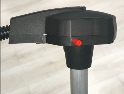
= '''<big>Sensor and cable sealing</big>''' = | |||
== '''<big>Sealing sensor of the current design</big>''' == | |||
You will need a sensor protective cover and a seal from the kit.<gallery widths="300" heights="300"> | |||
File:Protective_cover_for_wired_FLS.png|'''<big>Protective cover for wired FLS</big>''' | |||
File:New_design_seal.png|'''<big>Seal TD-150</big>''' | |||
</gallery>The cover is attached to the sensor head | |||
[[File:Wired_FLS_with_protective_cover.png|none|thumb|411x411px|'''<big>Wired FLS with protective cover</big>''']] | |||
Then the seal itself is fixed in a special hole (it must be inserted to the end, with the '''closed end facing outwards''')<gallery widths="400" heights="400"> | |||
File:Installing_a_seal_on_a_wired_FLS.png|'''<big>Installing a seal on a wired FLS</big>''' | |||
File:Installed_seal_on_the_wired_FLS.png|'''<big>Installed seal on a wired FLS</big>''' | |||
</gallery>To remove the seal, screw the special key from the kit into it (you can also use any self-tapping screw of a suitable size) and pull it towards you. | |||
[[File:Removal_of_the_seal_of_the_wired_FLS.png|none|thumb|515x515px|'''<big>Removal of the seal of the wired FLS</big>''']] | |||
[[File:Seal_after_removal.png|none|thumb|'''<big>Seal after removal</big>''']] | |||
Thus, it will be impossible to remove the seal without damaging it. This provides additional protection against unauthorized access. | |||
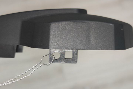
=== '''<big>Alternative sealing of a current sample sensor</big>''' === | |||
Also included with the sensor of the current sample is an alternative seal if a numbered seal is required. | |||
* It is necessary to pass the cable through the hole in the sensor cover | |||
* [[File:Alternative_sealing_of_wired_FLS_step_1.png|frameless|432x432px]] | |||
* Pass both ends of the cable through the hole in the sensor head | |||
* [[File:Alternative_sealing_of_wired_FLS_step_2.png|frameless|435x435px]] | |||
* Pass both ends through the seal, tighten the cable and install the seal by pressing on the protruding part | |||
* [[File:Alternative_sealing_of_wired_FLS_step_3.png|frameless|555x555px]] | |||
== '''<big>Sealing sensor of the former design</big>''' == | |||
[[File:Sealing_sensor_of_the_former_design.png|frameless|512x512px]] | |||
== '''<big>Cable sealing</big>''' == | |||
To seal the sensor connector, insert a plastic seal into the special hole on the sensor connector | |||
[[File:Wire_sealing.png|frameless|493x493px]] | |||
= '''<big>Updating the sensor firmware</big>''' = | |||
'''[https://docs.google.com/document/d/16KhS0ZV5Hrb44J66LmGOy7Gy2TKcuEqU/edit?usp=sharing&ouid=116383505004193584732&rtpof=true&sd=true Firmware update instructions]''' | |||
'''[https://youtu.be/BVCs-LiWLVs There is also a video instructional guide]''' | |||
'''You can find the latest firmware version in the [https://www.fmeter.ru/en/download/#td150 downloads section of our website]''' | |||
= '''<big>Common problems and solutions</big>''' = | |||
== '''<big>Level 7000</big>''' == | |||
'''Error Code 7000: Short Circuit.''' This error indicates that water has infiltrated the sensor head, for example, due to improper calibration practices such as inverting the sensor and introducing water into the sensor tubes, akin to the calibration method used for fuel sensors. '''This practice is strictly prohibited.''' Alternatively, the error may occur if foreign particles have entered between the tubes, causing a short circuit. | |||
You should clean the sensor tubes—preferably by blowing them out through the drainage holes using compressed air. | |||
If this error occurred after the start of operation of the sensor, it means that most likely these impurities got into the sensor tubes from the container and in this case it is also needed to ensure that the tank itself doesn't contain any contaminations. Clean the container, if necessary. Note that an ALS installed outside a contaminated container may function correctly, but the same sensor installed in such container may generate this error code. | |||
== '''<big>Level 6500</big>''' == | |||
This code may indicate that the tubes have lost contact. This error code may be generated immediately after cutting the tubes. In this case, simply calibrate the sensor. | |||
If this does not help, check the CNT. If the CNT is below 10,000, it is very likely that the tubes are not in contact with the sensor board. | |||
Take a photo of the sensor head (the sensor serial number should be visible), its tubes (the correspondence or discrepancy of the tubes length should be clearly visible), take a screenshot of the main screen of the sensor and the Settings menu page in the application and send these data to tech support. | |||
== '''<big>The sensor does not connect or is not recognized in the application</big>''' == | |||
If the sensor does not connect to the configurator, do the following: | |||
* Make sure that the correct COM port number is selected and that drivers and libraries are installed (STMicroelectronics Virtual COM Port ('''1''')(C200M) or USB-SERIAL CH341A ('''2''')(C200M2) in the COM and LPT ports section of the Windows device manager "to enter this menu, press '''win+r''' and enter '''devmgmt.msc''' and press '''OK''' ('''3''') and then expand the com ports submenu ('''4''')" | |||
** [[File:Com_ports_connected.png|frameless|786x786px]] | |||
** [[File:Com_ports_selection.png|frameless|722x722px]] | |||
** If possible, connect another sensor that is sure to work; if it connects, then there are no problems with the COM port or converter | |||
** Connect another USB cable to the C200M (ADD PWR connector); check if the USB cable is working | |||
** If another converter is used, ensure that sufficient power is supplied to the sensor (12 volts is optimal) | |||
** When connecting the sensor, press Search for sensors within 15 seconds after power is applied to the sensor | |||
** If the above does not help, reflash the FW of the sensor | |||
** If you cannot complete the firmware, contact our technical support | |||
== '''<big>Checking the connection between the sensor and the terminal via RS-485</big>''' == | |||
If the sensor, for some reason, after you have configured everything correctly, does not transmit data to the terminal, you need to find out whether data is being exchanged between devices. | |||
To do this, connect the sensor to the terminal via RS-485. Connect power to both devices. | |||
After that, take the RS-485-USB converter and connect it between the sensor and the terminal as shown below: | |||
For RS-485, lines A and B of the converter must be connected to lines A and B of the sensor | |||
[[File:RS-485_Logging_Connections_.png|none|thumb|648x648px|'''<big>RS-485 Logging Connections</big>''']] | |||
Run [https://drive.google.com/file/d/10i7v4TZ9-JDJYPAh-9JSh4x6vkM93BVV/view?usp=sharing terminal.exe] and configure the COM port as shown below: | |||
Baud rate – 19200, Parity – None, Stop-bits – 1, Handshaking – None | |||
Also, check HEX or ASCII depending on the format in which information from the sensor will be transmitted. For all sensors except the TD-600 configured in RS-232 mode, you must select HEX. | |||
After connecting the converter correctly, select the COM port and click Connect. If the sensor is polled by the terminal and responds, then everything is in order. | |||
[[File:Sensor_responds_to_the_terminal_via_RS-485.png|none|thumb|572x572px|'''<big>Sensor responds to the terminal via RS-485</big>''']] | |||
If there is no communication between the two devices, try polling the sensor manually. | |||
To do this, enter the request '''31$01$06$6C''' for the sensor with network address 1 and click '''Send''' | |||
[[File:Sending_a_request_to_the_sensor.png|none|thumb|585x585px|'''<big>Sending a request to the sensor</big>''']] | |||
The structure of the request depends on the network address of the sensor. If you change the sensor address to 255, for example, then the request would look like this | |||
'''31$FF$06$29''' | |||
'''FF''' - 255 in HEX | |||
'''29''' - '''CRC''' checksum calculated for a specific request | |||
In order to calculate the checksum, you can go to the '''[https://crccalc.com/ crccalc]''' website and enter your request without the '''$''' sign, select HEX, CRC-8/MAXIM and click Calc CRC-8 | |||
[[File:CRC_calculation_for_address_255.png|none|thumb|665x665px|'''<big>CRC calculation for address 255</big>''']] | |||
If the sensor is polled by the terminal and responds, then everything is in order. | |||
If the sensor does not respond to the terminal, but responds to a request you send manually, you should check your terminal's RS-485 ports. | |||
If the sensor does not respond to anything, the standard ALS diagnostic procedure should be carried out. | |||
= '''<big>Description of the LLS protocol</big>''' = | |||
The protocol is described in this [https://docs.google.com/spreadsheets/d/1maRSrToEaYtOP0sQz69Qq3e0iA0dBRos/edit?usp=drive_link&ouid=113197106569288024895&rtpof=true&sd=true document] | |||
Example of a request and response for 1 network address: | |||
Request: '''''31 01 06 6C''''' | |||
Response from sensor: '''''3E 01 06 19 01 00 92 5D BE''''' | |||
= '''<big>Purpose of contacts and wires</big>''' = | |||
[[File:Pinout_TD-150.png|frameless|828x828px]] | |||
= '''<big>Useful links</big>''' = | |||
*'''<big>[https://www.fmeter.ru/download/_ftp/eng/water-level-sensor/Datasheet%20Escort%20ALS.pdf?v=220225205325#page=21 Technical data sheet of the device]</big>''' | |||
* '''<big>[https://www.fmeter.ru/en/produktsiya/water-level-sensor/escort-als/#active Product page]</big>''' | |||
* '''<big>[https://www.fmeter.ru/en/download/#ALS Download materials]</big>''' | |||
Latest revision as of 12:45, 5 February 2026
Definition and purpose of the sensor

Escort's high-precision water level sensors ("WLS" or "ALS", also referred to as "gauges" or "sensors") are designed to determine the fill level of water in containers, tanks, and storage vessels. The ALS gauge is used in specialized equipment as a water level indicator and in industry as a level sensor for liquids with properties similar to water. The measurement principle of Escort's WLS is capacitive, relying on the dielectric permittivity of the medium; in this case, it measures the level of non-aggressive liquids such as water, aqueous solutions, liquid fertilizers, etc. Materials in contact with the measured liquid include aluminum alloy (AD-31) and polyacetal (PA-6).
Note: The ALS sensor is not intended for use with liquid food products, such as milk, juices, fermented dairy products, etc., as it is not certified for these applications.
More detailed technical characteristics are presented in the technical data sheet of the device
Basic terms and concepts
Aqua Level Sensor (ALS) - device which is used for measuring water level.
Serial number - code consisting of letters and numbers assigned to a device (sensor).
CNT - an oscillatory circuit, thanks to which the basic level of filling of the sensor measuring tubes with water is calculated. This level is converted to a final value determined by the data interface.
Data transfer protocol - a set of specific logical-level rules or conventions that govern the exchange of data between different programs or devices. For TD-150, the main transmission protocol is LLS via the RS-485 interface.
Data transfer mode - this is a type of boundary between two objects or nodes, which are regulated by a special accepted standard and implemented using established methods, tools and rules. TD-150 has the following operating modes:
- RS-485 (Passive and Active)
- Analog
- Frequency
Interface - a physical connection method and/or a set of software tools that allows data to be transferred between two or more devices.
RS-485 - digital data transmission mode. The sensor waits for a corresponding request from the receiving device. Works using the LLS protocol. Based on CNT, a value is generated in conventional units of the selected range (1-1023 units or 1-4095 units)
Converter - digital converter RS-485 to USB (С200М или С200М2) for configuring wired sensors.
Active (periodic) RS-485 - operating mode in which the sensor, without waiting for a request from the receiver, itself transmits packets with command data within 2 seconds.
Analog - mode in which a corresponding voltage is generated based on the CNT in the approximate range of 0.2-9V.
Frequency - mode in which the corresponding frequency in Hz is generated based on the CNT (301-1323 Hz with a value range of 1-1023; 301-4395 Hz with a value range of 1-4095).
Navigation terminal - the main element of the system for monitoring the operation of transportation carried out by means of satellite communication. Without it, it is impossible to control transportation, to determine the coordinates of the vehicle location. It collects information from sensors and on-board system of the vehicle, and then transmits it to the device/server, which belong to the controlling specialist.
Preparation
Why Should the Sensor Be Installed at the Geometric Center of a Mobile Tank?
The highest point of the tank should be selected to ensure the sensor can measure the entire liquid level within the tank without any blind spots.
The liquid level readings from a sensor installed at the center of the tank will be least affected by movement and sloshing of the liquid inside the tank.
If it is not possible to install the sensor at the center of the tank, consider the option of installing two sensors diagonally at opposite corners. When liquid shifts towards one side of the tank, the corresponding sensor will show an increase in level, while the opposite sensor will show a decrease. This way, the average liquid level will remain unchanged.
Video Example:
Attention: Before starting the calibration, the vehicle/tank must be positioned level with respect to the horizon, i.e., on a flat surface without any incline.
If the tank has an irregular shape, the sensor should be installed at the point of maximum depth, as close to the geometric center as possible.


When installation at the center is not possible – use two or more sensors.
To increase accuracy and reduce level fluctuations, two sensors are installed in one tank. This solution is primarily used for tanks with a capacity of more than 600 liters and a length of at least 1500 mm. Sensors should not be installed directly against the tank walls.
Additionally, two or more sensors should be installed if it is not possible to position a sensor at the center of the tank and/or if the tank has an elongated shape, meaning the length of the tank is significantly greater than its height.

Note: Installing a single sensor in an elongated tank will allow for detecting draining and filling. However, increased level fluctuations during movement may prevent the monitoring platform from accurately calculating the liquid consumption. Therefore, installing two sensors is preferred.
Installation locations in tanks of complex shapes
Saddle-Style Fuel Tanks
In this case, it is desirable to install two fuel level sensors in the deepest places along the geometric center of the depressions


Cylindrical tank
In this case, the sensor must be installed in the geometric center of the tank.


Long cylindrical tank
In the case of elongated cylindrical tanks, to improve readings while driving, it is necessary to install two sensors at an equal distance from the geometric center of the tank.


Ladder shape tank
If there is a difference in height in the tank and there is no common bed, it may be necessary to install two water level sensors.


Ladder shape tank's tank calibration
During calibration, two tables need to be created: one for "Sensor 1" (ДУВ 1) and another for "Sensor 2" (ДУВ 2).
Let's assume the calibration step is 10 liters.
At the beginning of the calibration, when the liquid is in the "Red Zone," level changes will only occur on "Sensor 2," so we directly add the calibration steps of 10 liters to the table for "Sensor 2."
When the liquid is in the "Yellow Zone," changes will occur on both "Sensor 1" and "Sensor 2." In this interval, we record changes in both tables with half-step increments. This means we add 10 liters, but in each sensor's table, we record 5 liters.
When the liquid is in the "Green Zone," changes will occur only on "Sensor 1," so we directly add the calibration steps of 10 liters to the table for "Sensor 1."
On the platform, "Sensor 1" and "Sensor 2" are configured as separate sensors with their own tables, and then a third virtual sensor is created, which sums the liters from both sensors. An example of configuring two sensors on the platform is shown. in this instruction..

Preparing the sensor
Preparing the sensor tubes
Before calibrating the sensor, you should determine the future length of the measuring tubes in accordance with the height of the tank and cut or extend them. The length of the tubes should be calculated according to the following formula:
L = H - 15 mm,
where L - tubes length after changing the length
and
H - height of the tank at the installation point.
ATTENTION!!! The ALS sensor is available with tube lengths of 950mm, 1450mm, 1950mm, and 2450mm.
Use a hacksaw to cut the tubes . Be careful during the cutting process to avoid damaging the connection between the tubes and the PCB inside the sensor head, as well as the insulating material of the inner tube.
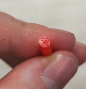
After cutting the sensor tubes, use the special insulating heat shrink cap included with the sensor for insulating the inner tube. Use a heat gun or any other heating element to shrink the cap properly.
Example:
Take this plastic insulation cap

Cover the inner tube with this cap
.jpg)
Press down on cover cap

Use hot air gun to finish the insultion

The extension of the water level sensor tubes is not allowed due to the design features of the inner tube.
Connection dimensions

Connection to the sensor, setup, calibration and calibration via the configurator on a PC
Installation of the configurator and connection to the sensor
The sensor can be configured using the configurator on a PC (From here onwards- "configurator").
Connect the sensor to the USB-RS-485 converter using a 6-pin MOLEX connector or using cable clamps if a cable route is connected to the sensor. Orange wire is line A of the RS-485 sensor interface, white wire is line B of the RS-485 sensor interface, black wire is GND, red is PWR.


We recommend using our Escort C200M/C200M2 USB-RS-485 converter, since we cannot guarantee 100% compatibility of our devices with converters from other brands.
When working with a laptop, we recommend connecting it to the power supply and/or connecting an additional USB cable to the ADD connector of the PWR C200M. Otherwise, there may not be enough power to operate the sensor and transmitter.
Along with installing the configurator 1.0.2.38, the drivers for the C200M will be installed automatically.
If you use C200M2 on Windows 10 and 11 operating systems, drivers should be installed automatically from Windows Update, on the Windows 7 operating system and below, you may need to disable the electronic signature of drivers and manually install drivers for the С200M2.
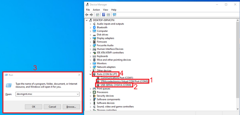
If the driver was installed correctly, then after connecting the converter to your PC/laptop, you will see the STMicroelectronics Virtual COM Port (1)(C200M) or USB-SERIAL CH341A (2)(C200M2) device in the COM and LPT ports section of the Windows device manager " to enter this menu, press win+r and enter devmgmt.msc and press OK (3) and then expand the com ports submenu (4)"
The com port number displayed in this menu is also needed to connect the sensor.

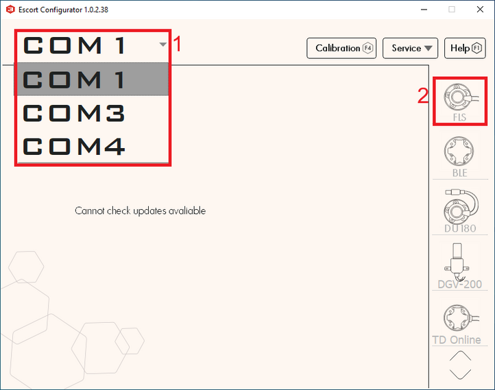
After connecting the converter, sensor to it and checking the installation of drivers by checking the com port number of the converter, you need to open the configurator, select the desired com port which we could find in the device manager (1) and press the FLS button (2).

The connection to the FLS should be made within 15 seconds after the sensor has been connected to power, if the sensor operating mode has been changed from RS-485 to any other.
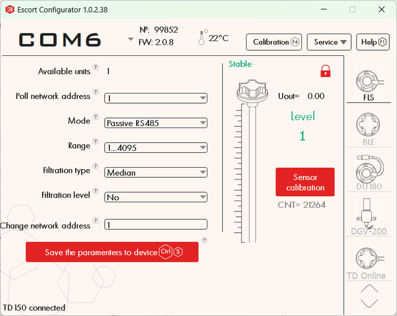
After connecting the sensor you should see this menu:

- Sensor serial number
- Sensor firmware version (FW)
- Sensor temperature
- Current sensor level
- Current CNT level (raw level value) of the sensor
- LLS network addresses connected to this converter (if there is more than one address in this list, it means either more than one sensor is connected to the line at the same time or there is interference on the line, in this case it is necessary to check the connection to the ALS for the presence of other conflicting devices and it is necessary to close other programs using the com ports for example tracker configurator)
- Network address of the polled sensor (This address is used when connecting in RS485 mode)
- Current sensor operating mode
- Current range of output values (1-1023 or 1-4095)
- Current filtration type and degree
- Connected sensor model
Sensor calibration

After you have lengthened or shortened the sensor tubes, you need to carry out the sensor calibration procedure.
To do this you need:
- Go to menu "Sensor calibration"

- IMPORTANT! DO NOT INVERT THE SENSOR OR INTRODUCE LIQUID INTO THE INTERNAL TUBING IN A MANNER ANALOGOUS TO FUEL SENSORS. CALIBRATE THE SENSOR EXCLUSIVELY BY SUBMERGING THE TURBOC INTO A RESERVOIR CONTAINING THE FLUID IN WHICH THE SENSOR WILL BE OPERATED.
- The water level sensor is designed based on a fuel sensor platform; therefore, the calibration menu will display the label "Calibration without fuel."
- Wait for the CNT level to stabilize (1)
- Deselect the "Calibration without fuel" slider (2)
- Click "Full" (3)
- The value "Full" (4) should change to a value close to the value of the current CNT (1), but not equal to it, since this value is set according to the temperature compensation of the sensor

- Empty the pipes of fuel, leave the centralizer in the pipes
- Wait for CNT to stabilize (1)
- Click "Empty" (2)
- The value "Empty" (3) should change to a value close to the value of the current CNT (1), but not equal to it, since this value is set according to the temperature compensation of the sensor
- Click "OK"
![]()
- The sensor level should display as 1, the sensor calibration process is complete. Thus, CNT should increase as the sensor tubes fill with fuel. It should change from a value close to the Empty calibration value to the Full calibration value.
WARNING! For the ALS sensor, it is strongly advised to avoid using the automatic dry calibration function (formally labeled as "Calibration without fuel").
Setting the calibration value Full and Empty manually
We do not recommend using this functionality, but you can set the Full and Empty calibration values manually to save time when you are using sensors of the same length in the same tanks.
Attention!!! Setting calibration values manually will most likely increase the sensor error! We do not recommend doing this!
To do this, enter the Full and Empty calibration values of the previously calibrated sensor into the appropriate fields in the configurator.


![]()
Setting the mode, range and network address
Setting the mode
In the main menu, you can change the operating mode of the sensor. The name of the mode coincides with the interface that is used to physically connect the sensor to the GPS terminal
Select the mode you need(1) and click “Save parameters to device”(2)

- Passive RS485 should be selected when you plan to connect to line A and B of the terminal's RS-485 interface. The terminal must have the function of polling sensors, for example, requesting information from them. The terminal must be able to interrogate sensors in accordance with the LLS protocol.
- Frequency mode is used when connecting to a GPS terminal to inputs that can receive and read signals in the range 300 Hz … 1323 Hz or 300 Hz … 4395 Hz.
- Active RS485 mode should be used if the terminal has an RS-485 connection interface, but cannot independently poll the sensor, for example, request information from it; the sensor will send its readings independently every 2 seconds.
Note: The analog output of the ALS is always active on the green wire in the 0.2-9V range, there is no need to turn it on separately
Setting the range
If you are configuring the sensor to operate in RS-485, Active RS-485, or Frequency modes, you can select the range 1-1023 or 1-4095 (1) . In frequency mode, the range will be from 300Hz to 1323Hz or 300Hz to 4395Hz.
After changing the range, click “Save the parameters to device” (2).

The range 1-1023 is most often used for sensors that are shorter than 1 meter. However, if we are talking about a stationary tank, the height of which is small, but the length and width are more than 2-3 m, it is better to choose the range 1-4095.
Setting the network address
The default network address of the sensor is 1; if more than one unit is installed or other ALS devices are added, the network address on the sensor may need to be changed. The network address of each sensor must also be specified in the settings of the receiving device (navigation terminal).
Attention!!! There cannot be two devices with the same network address on the same line; this will cause a conflict.
To change the network address, enter a new address in the range 0-255 in the “Change network address” field (1) and click “Save the parameters to device” (2), after which the configurator should switch to the new sensor address and display the new sensor address in the field "Available units" (3) and "Poll network address" (4).


Tank calibration
The process is carried out similarly to the calibration procedure used with fuel sensors. For example, when using a sensor based on the TD-150
Setting and removing a password
If necessary, you can set a password on the sensor to change settings.
To do this:
- Click on the "Service" button (1) and then "Security" (2)

- In the menu that opens, you can enter a password consisting of numbers and then click set password. Also note that the password cannot start with 0.
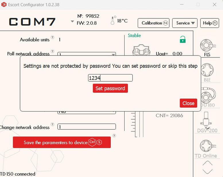
- After successfully setting the password, a red lock should appear next to the FLS icon


PLEASE NOTE THAT THE PASSWORD RESET PROCEDURE CAN BE VERY TIME-CONSUMING. WE RECOMMEND THAT YOU TAKE A RESPONSIBLE APPROACH IN SETTING YOUR PASSWORD AND SAVING IT.
To change the settings of a password-protected sensor or remove a password, you need to perform the password removal procedure
- Click on the "Service" button (1) and then "Security" (2)
- In the menu that opens, enter your password (or if you have lost your password, the master password provided by technical support) and click "Remove password"

- If the password was successfully removed, the lock should turn green

Attention! By default, there is no password set on the sensor! If you connected the sensor and a password was already set on it, contact technical support.
Connecting the sensor to the GPS terminal
Connection diagrams
In order to connect the sensor to the GPS terminal and to the power source, use the diagram presented below
[[:File:Wired RS-485 no R.png|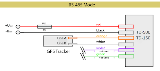 ]]
]]


The ALS sensor has analog mode always enabled; it does not need to be enabled in the configurator!
Sensor and cable sealing
Sealing sensor of the current design
You will need a sensor protective cover and a seal from the kit.
-

Protective cover for wired FLS
-
Seal TD-150


The cover is attached to the sensor head

Then the seal itself is fixed in a special hole (it must be inserted to the end, with the closed end facing outwards)
-
Installing a seal on a wired FLS
-

Installed seal on a wired FLS


To remove the seal, screw the special key from the kit into it (you can also use any self-tapping screw of a suitable size) and pull it towards you.


Thus, it will be impossible to remove the seal without damaging it. This provides additional protection against unauthorized access.
Alternative sealing of a current sample sensor
Also included with the sensor of the current sample is an alternative seal if a numbered seal is required.
- It is necessary to pass the cable through the hole in the sensor cover

- Pass both ends of the cable through the hole in the sensor head


- Pass both ends through the seal, tighten the cable and install the seal by pressing on the protruding part


Sealing sensor of the former design

Cable sealing
To seal the sensor connector, insert a plastic seal into the special hole on the sensor connector

Updating the sensor firmware
There is also a video instructional guide
You can find the latest firmware version in the downloads section of our website
Common problems and solutions
Level 7000
Error Code 7000: Short Circuit. This error indicates that water has infiltrated the sensor head, for example, due to improper calibration practices such as inverting the sensor and introducing water into the sensor tubes, akin to the calibration method used for fuel sensors. This practice is strictly prohibited. Alternatively, the error may occur if foreign particles have entered between the tubes, causing a short circuit.
You should clean the sensor tubes—preferably by blowing them out through the drainage holes using compressed air.
If this error occurred after the start of operation of the sensor, it means that most likely these impurities got into the sensor tubes from the container and in this case it is also needed to ensure that the tank itself doesn't contain any contaminations. Clean the container, if necessary. Note that an ALS installed outside a contaminated container may function correctly, but the same sensor installed in such container may generate this error code.
Level 6500
This code may indicate that the tubes have lost contact. This error code may be generated immediately after cutting the tubes. In this case, simply calibrate the sensor.
If this does not help, check the CNT. If the CNT is below 10,000, it is very likely that the tubes are not in contact with the sensor board.
Take a photo of the sensor head (the sensor serial number should be visible), its tubes (the correspondence or discrepancy of the tubes length should be clearly visible), take a screenshot of the main screen of the sensor and the Settings menu page in the application and send these data to tech support.
The sensor does not connect or is not recognized in the application
If the sensor does not connect to the configurator, do the following:
- Make sure that the correct COM port number is selected and that drivers and libraries are installed (STMicroelectronics Virtual COM Port (1)(C200M) or USB-SERIAL CH341A (2)(C200M2) in the COM and LPT ports section of the Windows device manager "to enter this menu, press win+r and enter devmgmt.msc and press OK (3) and then expand the com ports submenu (4)"
- If possible, connect another sensor that is sure to work; if it connects, then there are no problems with the COM port or converter
- Connect another USB cable to the C200M (ADD PWR connector); check if the USB cable is working
- If another converter is used, ensure that sufficient power is supplied to the sensor (12 volts is optimal)
- When connecting the sensor, press Search for sensors within 15 seconds after power is applied to the sensor
- If the above does not help, reflash the FW of the sensor
- If you cannot complete the firmware, contact our technical support
Checking the connection between the sensor and the terminal via RS-485
If the sensor, for some reason, after you have configured everything correctly, does not transmit data to the terminal, you need to find out whether data is being exchanged between devices.
To do this, connect the sensor to the terminal via RS-485. Connect power to both devices.
After that, take the RS-485-USB converter and connect it between the sensor and the terminal as shown below:
For RS-485, lines A and B of the converter must be connected to lines A and B of the sensor

Run terminal.exe and configure the COM port as shown below:
Baud rate – 19200, Parity – None, Stop-bits – 1, Handshaking – None
Also, check HEX or ASCII depending on the format in which information from the sensor will be transmitted. For all sensors except the TD-600 configured in RS-232 mode, you must select HEX.
After connecting the converter correctly, select the COM port and click Connect. If the sensor is polled by the terminal and responds, then everything is in order.

If there is no communication between the two devices, try polling the sensor manually.
To do this, enter the request 31$01$06$6C for the sensor with network address 1 and click Send

The structure of the request depends on the network address of the sensor. If you change the sensor address to 255, for example, then the request would look like this
31$FF$06$29
FF - 255 in HEX
29 - CRC checksum calculated for a specific request
In order to calculate the checksum, you can go to the crccalc website and enter your request without the $ sign, select HEX, CRC-8/MAXIM and click Calc CRC-8

If the sensor is polled by the terminal and responds, then everything is in order.
If the sensor does not respond to the terminal, but responds to a request you send manually, you should check your terminal's RS-485 ports.
If the sensor does not respond to anything, the standard ALS diagnostic procedure should be carried out.
Description of the LLS protocol
The protocol is described in this document
Example of a request and response for 1 network address:
Request: 31 01 06 6C
Response from sensor: 3E 01 06 19 01 00 92 5D BE
Purpose of contacts and wires
