
TD-BLE: Difference between revisions
No edit summary |
|||
| (153 intermediate revisions by 4 users not shown) | |||
| Line 1: | Line 1: | ||
[[RU:TD-BLE| Русская версия]] | [[RU:TD-BLE| Русская версия]] | ||
[[es:TD-BLE| Versión en español]] | [[es:TD-BLE| Versión en español]] | ||
[[File:TD-BLE.png.png|thumb|Current TD-BLE design]] | [[File:TD-BLE.png.png|thumb|Current TD-BLE design]] | ||
= <big>'''Definition and purpose of the sensor'''</big> = | = <big>'''Definition and purpose of the sensor'''</big> = | ||
'''Escort''' fuel level sensors (FLS or sensors) are designed to determine the filling level of petroleum products in fuel tanks, reservoirs and storage tanks. '''TD-BLE''' (sensor) is used in transportation as a fuel level meter and in the industry - as a level meter for any light petroleum products. Escort FLS measurement type is capacitive. Its readings are based on the dielectric constant of the medium in which it operates; in this case, the medium is various types of light petroleum products (gasoline, diesel, kerosene, motor oil). | '''Escort''' fuel level sensors (FLS or sensors) are designed to determine the filling level of petroleum products in fuel tanks, reservoirs and storage tanks. '''TD-BLE''' (sensor) is used in transportation as a fuel level meter and in the industry - as a level meter for any light petroleum products. Escort FLS measurement type is capacitive. Its readings are based on the dielectric constant of the medium in which it operates; in this case, the medium is various types of light petroleum products (gasoline, diesel, kerosene, motor oil). | ||
| Line 28: | Line 26: | ||
'''Connection mode''' - is a data transfer mode in which the transmitter waits for a connection to the receiving device in order to begin transmitting data packets. | '''Connection mode''' - is a data transfer mode in which the transmitter waits for a connection to the receiving device in order to begin transmitting data packets. | ||
'''[[База BLE-RS485]]''' - is a device that relays data transfer and converts it from a Bluetooth packet into a data packet transmitted via the RS-485 interface in accordance with the LLS protocol. | '''[[База BLE-RS485|Base BLE-RS485]]''' - is a device that relays data transfer and converts it from a Bluetooth packet into a data packet transmitted via the RS-485 interface in accordance with the LLS protocol. | ||
''' | '''Base BA-BLE''' - is a device that relays data transfer and converts it from a Bluetooth packet into a data packet transmitted via RS-485 and RS-232 interfaces in accordance with the LLS protocol. | ||
= '''<big>TD-BLE sensor's design</big>''' = | = '''<big>TD-BLE sensor's design</big>''' = | ||
| Line 49: | Line 47: | ||
== '''<big>Connecting sensor</big>''' == | == '''<big>Connecting sensor</big>''' == | ||
[[File:Connection GIF.gif]] | |||
Press the '''Sensor Settings''' button. Next, select '''TD-BLE'''. | Press the '''Sensor Settings''' button. Next, select '''TD-BLE'''. | ||
[[ | [[File:Sensor settings. Main page.png|frameless]] [[File:ConnectionTDBLE.png|frameless]] | ||
Find the required sensor by typing the last 6 digits of its serial number. You can find the serial number on the sensor head. | Find the required sensor by typing the last 6 digits of its serial number. You can find the serial number on the sensor head. | ||
| Line 59: | Line 57: | ||
You can also simply select the required sensor from the list and click the Connect button. On an Android device, you can click on the sensors name, and a package of data received in advertising mode will be displayed. | You can also simply select the required sensor from the list and click the Connect button. On an Android device, you can click on the sensors name, and a package of data received in advertising mode will be displayed. | ||
[[ | [[File:SensorSelection.png|frameless]] [[File:SensorAdvData.png|frameless]] | ||
== '''<big>Setting a password</big>''' == | == '''<big>Setting a password</big>''' == | ||
| Line 68: | Line 64: | ||
You can set, change and delete a password in the '''Additional Features'''. | You can set, change and delete a password in the '''Additional Features'''. | ||
[[ | [[File:SensorAddFeatures.png|frameless]] | ||
Then, in the field that appears named "Password for changing settings", enter the password that you want be used later and click '''Enter'''. | Then, in the field that appears named "Password for changing settings", enter the password that you want be used later and click '''Enter'''. | ||
[[ | [[File:SensorPasswordChangeMenu.png|frameless]]<blockquote>'''<u><big>PLEASE NOTE THAT THE PASSWORD RESET PROCEDURE CAN BE VERY TIME-CONSUMING. WE RECOMMEND THAT YOU TAKE A RESPONSIBLE APPROACH IN SETTING YOUR PASSWORD AND SAVING IT.</big></u>'''</blockquote>'''<big>Also note that the password cannot start with 0.</big>''' | ||
To delete a previously set password, you must enter it in the Password field, and then press the '''Enter''' and then the '''Delete''' buttons. | To delete a previously set password, you must enter it in the Password field, and then press the '''Enter''' and then the '''Delete''' buttons. | ||
| Line 88: | Line 84: | ||
# '''Vbat''' or sensor battery charge (3.5V or higher indicates the battery is fully charged; 3.2V or lower indicates the battery is low and should be replaced) | # '''Vbat''' or sensor battery charge (3.5V or higher indicates the battery is fully charged; 3.2V or lower indicates the battery is low and should be replaced) | ||
# Sensor '''CNT''' (its purpose will be explained later in the manual) | # Sensor '''CNT''' (its purpose will be explained later in the manual) | ||
# Graphic scale of sensor filling | |||
# The '''sensor's MAC address''' is used to connect the sensor to compatible external devices | # The '''sensor's MAC address''' is used to connect the sensor to compatible external devices | ||
<gallery widths=" | <gallery widths="400" heights="800" mode="nolines"> | ||
File:DataAndroid.png|<big>'''Page "Data" (Android)'''</big> | |||
File:DataPageIos.png|<big>'''Page "Data" (iOS)'''</big> | |||
</gallery>'''The battery voltage drops to 3.2V for 10-15 seconds''' - this is normal (especially if this happens after rebooting the sensor by removing the sensor battery and then installing the battery back). This is due to the fact that all processes in the sensor (measuring level, temperature and battery voltage, as well as sending a data packet) are launched simultaneously, thus energy consumption increases, which leads to a temporary decrease in battery voltage. | </gallery> | ||
'''The battery voltage drops to 3.2V for 10-15 seconds''' - this is normal (especially if this happens after rebooting the sensor by removing the sensor battery and then installing the battery back). This is due to the fact that all processes in the sensor (measuring level, temperature and battery voltage, as well as sending a data packet) are launched simultaneously, thus energy consumption increases, which leads to a temporary decrease in battery voltage. | |||
= '''<big>Sensor calibration</big>''' = | = '''<big>Sensor calibration</big>''' = | ||
[[ | [[File:Callibration GIF.gif]] | ||
== '''<big>CNT. What happens when you calibrate a sensor?</big>''' == | == '''<big>CNT. What happens when you calibrate a sensor?</big>''' == | ||
After you have cut or extended the sensor tubes, you should calibrate it, that is, set the new '''Full''' and '''Empty''' calibration values. You can do this from the '''Settings''' menu on the sensor's main screen. | After you have cut or extended the sensor tubes, you should calibrate it, that is, set the new '''Full''' and '''Empty''' calibration values. You can do this from the '''Settings''' menu on the sensor's main screen. | ||
[[ | [[File:SettingsPageAndroid.png|frameless]] | ||
The sensor's raw data - current level or CNT - changes according to how much fuel is inside its tubes. | The sensor's raw data - current level or CNT - changes according to how much fuel is inside its tubes. | ||
| Line 107: | Line 106: | ||
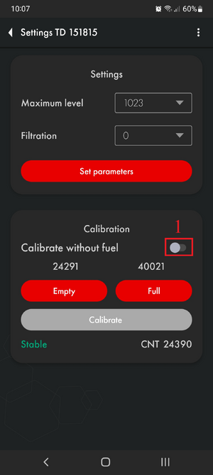
If the '''tubes are empty''' and “'''CNT (1) ≈ calibration value Empty (2)'''”, level 1 '''(3)''' will be displayed.<gallery mode="nolines" widths="400" heights="750"> | If the '''tubes are empty''' and “'''CNT (1) ≈ calibration value Empty (2)'''”, level 1 '''(3)''' will be displayed.<gallery mode="nolines" widths="400" heights="750"> | ||
File:SettingPageScreen.png|alt= | |||
File:DataLevel.png|alt= | |||
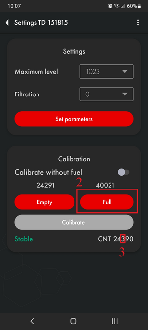
</gallery>If the '''tubes are full''' and “'''CNT (1) ≈ calibration value Full (2)'''”, level 1023 or 4095 '''(3)''' will be displayed.<gallery mode="nolines" widths="400" heights=" | </gallery>If the '''tubes are full''' and “'''CNT (1) ≈ calibration value Full (2)'''”, level 1023 or 4095 '''(3)''' will be displayed.<gallery mode="nolines" widths="400" heights="749"> | ||
File:SettingsFullCNT.png|alt= | |||
File:DataFullLevel.png|alt= | |||
</gallery> | </gallery> | ||
Thus, '''CNT''' should increase as the sensor tubes fill with fuel. It should change from a value close to the '''Empty''' calibration value to the '''Full''' calibration value. | Thus, '''CNT''' should increase as the sensor tubes fill with fuel. It should change from a value close to the '''Empty''' calibration value to the '''Full''' calibration value. | ||
[[ | [[File:TankEmptyFull.png|frameless|512x512px]]<blockquote><big>During sensor calibration, the current CNT is stored as a Full calibration value (if you pressed the '''Full''' button) or as an Empty calibration value (if you pressed the '''Empty''' button). Calibration values '''may''' differ from the current CNT after recording. A difference of ±1000 values is acceptable.</big></blockquote> | ||
== '''<big>How and why to calibrate sensors?</big>''' == | == '''<big>How and why to calibrate sensors?</big>''' == | ||
| Line 123: | Line 122: | ||
Therefore you should: | Therefore you should: | ||
* Insert the plastic centralizer provided into the tubes | |||
[[File:Centralizer.png]] [[File:Centralizer-Centrator.png|512x512px]] | |||
* Fill the tubes with fuel by covering the drain holes with electrical tape and turning the sensor upside down or immersing the sensor in fuel so that the fuel reaches the flange of the sensor (the drain holes are open). The first method is preferable<gallery widths="350" heights="300" mode="nolines"> | |||
File:Closing the drain holes, rotating the sensor, and filling the tubes with fuel.png|'''Closing the drain holes, rotating the sensor, and filling the tubes with fuel''' | |||
File:Filling the tubes by immersing the sensor in fuel (drain holes open).png|'''Filling the tubes by immersing the sensor in fuel (drain holes open)''' | |||
</gallery> | </gallery> | ||
* Switch the "Calibration without fuel" slider to the inactive position '''(1)''' and press the '''Full''' button '''(2)''' after the level becomes Stable or the third digit from the end stops changing (for at least 2 minutes) '''(3)'''<gallery mode="nolines" widths="300" heights="700"> | |||
File:CalibrationWithFuel.png|alt=|'''Disable the option "Calibrate without fuel"''' | |||
File:SettingsWithFuelFullStab.png|'''Click "Full" after the level has stabilized''' | |||
</gallery> | </gallery> | ||
* Then, drain the fuel from the tubes, wait 2-3 minutes, allowing the fuel to completely drain and the level to stabilize, and press '''"Empty"''' | |||
[[ | [[File:Unblocking drain holes.png|none|thumb|660x660px|'''<big>Unblocking drain holes</big>''']] | ||
[[File:SetEmpty.png|frameless]] | |||
== '''<big>Calibration without fuel</big>''' == | == '''<big>Calibration without fuel</big>''' == | ||
| Line 139: | Line 140: | ||
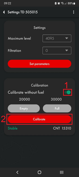
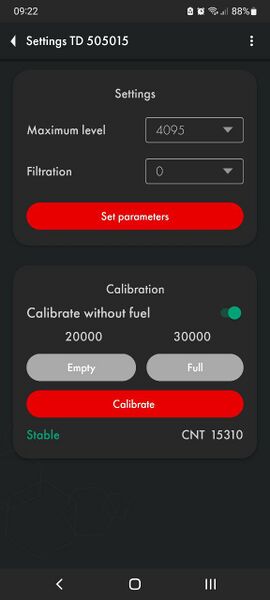
In this case, make sure that the sensor tubes are empty and there is no fuel in them, but the centralizer must be inserted into the tubes. Leave the '''"Calibrate without fuel"''' switch '''(1)''' active (green) and press '''"Calibrate" (2)''' . The values above the Empty and Full buttons will change automatically.<gallery widths="300" heights="600" mode="nolines"> | In this case, make sure that the sensor tubes are empty and there is no fuel in them, but the centralizer must be inserted into the tubes. Leave the '''"Calibrate without fuel"''' switch '''(1)''' active (green) and press '''"Calibrate" (2)''' . The values above the Empty and Full buttons will change automatically.<gallery widths="300" heights="600" mode="nolines"> | ||
File:Calibration without fuel.png|alt=|'''Calibration without fuel''' | |||
File:CNT before calibration.jpg|alt=|'''Calibration values BEFORE calibration without fuel''' | |||
File:CNT after calibration.jpg|alt=|'''Calibration values after calibration without fuel''' | |||
</gallery>If you calibrate the sensor without fuel, the operating range may change slightly. | </gallery>If you calibrate the sensor without fuel, the operating range may change slightly. | ||
| Line 161: | Line 162: | ||
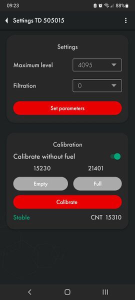
To change the range, open the Settings menu and select one of two options from the '''"Maximum Level"''' drop-down menu '''(1)'''. After this, click on the '''“Set parameters” button (2)'''.<gallery widths="350" heights="650" mode="nolines"> | To change the range, open the Settings menu and select one of two options from the '''"Maximum Level"''' drop-down menu '''(1)'''. After this, click on the '''“Set parameters” button (2)'''.<gallery widths="350" heights="650" mode="nolines"> | ||
File:SelectMaxLevel.png|alt= | |||
File:SetLevel.png|alt= | |||
</gallery> | </gallery> | ||
== '''<big>How to check if the calibration is correct?</big>''' == | == '''<big>How to check if the calibration is correct?</big>''' == | ||
The Empty calibration value must be at least 1.4 (after rounding) less than the Full calibration value. | The Empty calibration value must be at least 1.4 (after rounding) less than the Full calibration value.[[File:CorrectCalibration.png|none|thumb|667x667px|'''Correctly calibrated sensor''']] | ||
[[ | |||
= '''<big>Preparing the Tank and Sensor</big>''' = | = '''<big>Preparing the Tank and Sensor</big>''' = | ||
| Line 174: | Line 174: | ||
To prepare the tank you should: | To prepare the tank you should: | ||
* | * Empty the tank, clean and dry if necessary | ||
* ''' | * '''Remove fuel vapors and air from the tank''' (especially for a gasoline tank, but in the case of a diesel engine, this procedure should not be neglected, since gasoline could be added to the diesel); to do this, you can heat water to boiling point and direct the resulting steam into the tank or use carbon dioxide so that it displaces fuel vapors and air; ensure that any open flame sources are sufficiently far away from the fuel tank[[File:Removing fuel vapors.png|frameless|496x496px]] | ||
* ''' | * '''Find the geometric center of the tank and drill a hole''' in it using a '''ø3mm''' drill bit. Then, using a piece of stiff wire, examine the tank for the presence of partitions in it [[File:Choosing a location for installing the FLS.png|none|thumb|512x512px|'''<big>Choosing a location for installing the FLS</big>''']][[File:Little hole drilling.png|none|thumb|511x511px|'''<big>Drilling the tank and subsequent examination of the tank for the presence of partitions</big>''']] | ||
* | * If the space inside the tank in the selected location is free, '''drill a ø 35 mm hole''' using a bimetallic bit; When drilling, keep the bit tilted slightly to prevent the cut section from falling into the tank. Use a magnet to catch chips and prevent them from getting into the tank. [[File:Angled drilling.png|none|thumb|512x512px|'''<big>Drilling a hole at an angle</big>''']][[File:Removing metal part.png|none|thumb|512x512px|'''<big>Removing a drilled disc</big>''']] | ||
* | * If it is impossible to install the sensor in the geometric center of the tank, try choosing another location as close as possible to the geometric center of the tank; this point should coincide with the place where the height of the tank is maximum. This way you reduce the risk and amplitude of level fluctuations associated with fuel movement while driving. | ||
=== '''<big>Why should the sensor be mounted in the geometric center of the tank?</big>''' === | === '''<big>Why should the sensor be mounted in the geometric center of the tank?</big>''' === | ||
''' | '''The highest point must be chosen so that the sensor can measure the level of all the fuel inside the tank without any blind spots.''' | ||
The fuel level readings from a sensor installed in the center of the tank will be least affected by movement and fuel overflow in the tank. | |||
If it is not possible to install the sensor in the center of the tank, consider installing two sensors diagonally at two corners. When fuel flows to one side of the tank, the level on the corresponding sensor will rise, and on the opposite side, the level will correspondingly decrease, while the average level will remain unchanged. | |||
[https://youtu.be/ | [https://youtu.be/T0Pd6TOpuc8?si=xgub1mpjcEYOaHPp Video example of the importance of installing the sensor at the geometric center of the tank.] | ||
[[ | [[File:Sensor position and fuel flow.png|none|thumb|512x512px|'''<big>Sensor position and fuel flow</big>''']] | ||
<blockquote>''' | <blockquote>'''Attention:''' Before starting the calibration, the vehicle/fuel tank must be positioned flat in relation to the horizon, i.e. on a level surface without a slope.</blockquote>If the tank has an irregular geometric shape, the sensor must be installed at the maximum depth of the tank, closer to the geometric center. | ||
[[ | [[File:The sensor is installed in the highest place of the tank.png|none|thumb|648x648px|'''<big>The sensor is installed in the highest place of the tank</big>''']][[File:Ladder tank.png|frameless|784x784px]] | ||
[[File:Ladder tank I.png|frameless|752x752px]] | |||
==== '''<big>When installation in the center is impossible - two or more FLS.</big>''' ==== | ==== '''<big>When installation in the center is impossible - two or more FLS.</big>''' ==== | ||
To increase accuracy and reduce level fluctuations, install two sensors in one tank. This solution is mainly used in tanks with a capacity of more than 600 liters and having a length of 1500 mm. Sensors must not be installed close to the walls of the tank. | |||
Also, two or more sensors should be installed if it is not possible to install the sensor in the center of the tank and (or) the tank has an elongated shape, i.e. The length of the tank is significantly greater than its height. | |||
[[File:Two sensors installed diagonally.png|none|thumb|654x654px|'''<big>Two sensors installed diagonally</big>''']] | |||
'''Note.''' Installing a single sensor in an elongated tank will allow you to detect drains and refills. But increased level fluctuations while driving may not allow the monitoring platform to correctly read fuel consumption. Therefore, installing two sensors is preferable. | |||
== '''<big><u>Installation locations in tanks of complex shapes</u></big>''' == | |||
=== '''<big>Saddle-Style Fuel Tanks</big>''' === | |||
In this case, it is desirable to install two fuel level sensors in the deepest places along the geometric center of the depressions. | |||
[[File:Saddle shape.png|frameless|749x749px]] | |||
[[File:Saddle shape top view.png|frameless|749x749px]] | |||
[[File:Saddle shape side view.png|frameless|749x749px]] | |||
=== '''<big>Cylindrical tank</big>''' === | |||
In this case, the sensor must be installed in the geometric center of the tank. | |||
[[File:Cylindrical tank.png|frameless|750x750px]] | |||
[[File:Cylindrical tank top view.png|frameless|750x750px]] | |||
[[File:Cylindrical tank inside view.png|frameless|750x750px]] | |||
==== '''<big>Long cylindrical tank</big>''' ==== | |||
In the case of elongated cylindrical tanks, to improve readings while driving, it is necessary to install two sensors at an equal distance from the geometric center of the tank. | |||
[[File:Cylindrical tank long.png|frameless|750x750px]] | |||
[[File:Cylindrical tank long inside view.png|frameless|750x750px]] | |||
==== '''<big>Ladder shape tank</big>''' ==== | |||
If there is a difference in height in the tank and there is no common bed, it may be necessary to install two fuel level sensors. | |||
[[File:Ladder 2 tank.png|frameless|782x782px]] | |||
[[File:Ladder 2 tank inside view.png|frameless|750x750px]] | |||
===== '''<big>Ladder shape tank's tank calibration</big>''' ===== | |||
When calibrating, it is necessary to create two tables, one for "'''FLS 1'''" and the second for "'''FLS 2'''" | |||
Let's assume that the calibration step is 10 liters. | |||
At the beginning of calibration, when the fuel is in the "'''Red Zone'''", the level changes will only occur on "'''FLS 2'''", so we directly add calibration steps of 10 liters to the table for "'''FLS 2'''". | |||
When the fuel is in the "'''Yellow Zone'''" changes will occur on both "'''FLS 1'''" and "'''FLS 2'''", during this period we record changes in both tables with half a step, that is, we also fill in 10 liters, but we record 5 liters in the table of each sensor. | |||
When the fuel is in the "'''Green Zone'''" the changes will only occur on "'''FLS 1'''" so we directly add calibration steps of 10 liters to the table for "'''FLS 1'''". | |||
On the platform "'''FLS 1'''" and "'''FLS 2'''" are started as separate sensors with their own tables and then a third virtual sensor is created with the sum of liters for two sensors, an example of starting two FLS on the platform is shown [https://docs.google.com/document/d/14p9GYmY0D1Wjz0ZfJXO-soVfxRBP7EiY7TgibD6vmZQ/edit?usp=sharing in this instruction.] | |||
[[File:Ladder 2 tank calibration.png|frameless|750x750px]] | |||
== '''<big>Preparing the sensor</big>''' == | == '''<big>Preparing the sensor</big>''' == | ||
| Line 211: | Line 263: | ||
H - height of the tank at the installation point. <blockquote><big>'''ATTENTION!!!''' '''The minimum length''' of the tubes should not be less than '''15 cm (150 mm)'''. Otherwise, it will most likely not be possible to obtain adequate graphics. The maximum length of the tubes can reach '''6m.'''</big></blockquote> | H - height of the tank at the installation point. <blockquote><big>'''ATTENTION!!!''' '''The minimum length''' of the tubes should not be less than '''15 cm (150 mm)'''. Otherwise, it will most likely not be possible to obtain adequate graphics. The maximum length of the tubes can reach '''6m.'''</big></blockquote> | ||
[[ | [[File:Measuring height of the tank.png|none|thumb|938x938px|'''Measuring height of the tank''']] | ||
[[ | [[File:Measuring tubes length.png|none|thumb|942x942px|'''Measuring the length of tubes''']] | ||
Use a hacksaw to cut the tubes. When sawing, be careful not to damage the connection of the tubes to the circuit board inside the sensor head and to prevent metal shavings from falling into the tubes. | Use a hacksaw to cut the tubes. When sawing, be careful not to damage the connection of the tubes to the circuit board inside the sensor head and to prevent metal shavings from falling into the tubes. | ||
[[ | [[File:Cutting the tubes.gif|none|thumb|600x600px|'''Cutting the tubes''']] | ||
'''Avoid getting shavings inside the tubes - this may lead to a short circuit in the sensor; if this happens, blow the tubes with compressed air through the drainage holes under the sensor flange.''' Sand the edges of the tubes with sandpaper to remove any burrs or irregularities. | '''Avoid getting shavings inside the tubes - this may lead to a short circuit in the sensor; if this happens, blow the tubes with compressed air through the drainage holes under the sensor flange.''' Sand the edges of the tubes with sandpaper to remove any burrs or irregularities. | ||
You can use collet extension and an additional tube. to extend tubes length. | |||
[[ | |||
It is not reccomended to use more than '''one''' collect extension. | |||
[[File:Collet connection.png|none|thumb|875x875px|'''Collet connection''']] | |||
Inner nuts (yellow elements) are used to connect the inner tubes. Once they are installed and the studs are screwed into them, the tubes do not have to touch each other, but try to get them as close to each other as possible.. | Inner nuts (yellow elements) are used to connect the inner tubes. Once they are installed and the studs are screwed into them, the tubes do not have to touch each other, but try to get them as close to each other as possible.. | ||
[[ | [[File:Internal connection of the collet connection.png|none|thumb|748x748px|'''Internal connection of the collet connection''']] | ||
The outer coupling and the corresponding nuts must be securely tightened. '''The outer tubes should touch each other.''' | The outer coupling and the corresponding nuts must be securely tightened. '''The outer tubes should touch each other.''' | ||
[[ | [[File:Collet connection installed.png|none|thumb|752x752px|'''Collet connection installed''']] | ||
[https://www.youtube.com/watch?v= | |||
[https://www.youtube.com/watch?v=b_WtOHzKtDM Watch this video on our YouTube channel to see the real-time connection.] | |||
== '''<big>Connection dimensions of the TD-BLE of the former design</big>''' == | == '''<big>Connection dimensions of the TD-BLE of the former design</big>''' == | ||
[[ | [[File:Former design dimensions.png|frameless|512x512px]] | ||
== '''<big>Connection dimensions of the TD-BLE of the current design</big>''' == | == '''<big>Connection dimensions of the TD-BLE of the current design</big>''' == | ||
[[ | [[File:Current design dimensions.png|frameless|778x778px]] | ||
[[ | [[File:TD-BLE dimensions, current design .png]] | ||
= '''<big>Tank calibration</big>''' = | = '''<big>Tank calibration</big>''' = | ||
| Line 237: | Line 299: | ||
Install the sensor into the tank of the installed tube in the previously drilled hole ø 30-35 mm. Make sure '''the gasket is installed''' between the sensor and the tank. After this, screw the screws from the installation kit into the previously drilled ø 3mm holes.<gallery widths="700" heights="400"> | Install the sensor into the tank of the installed tube in the previously drilled hole ø 30-35 mm. Make sure '''the gasket is installed''' between the sensor and the tank. After this, screw the screws from the installation kit into the previously drilled ø 3mm holes.<gallery widths="700" heights="400"> | ||
File:Installing the sensor inside the tank.png|'''<big>Installing the sensor inside the tank</big>''' | |||
File:Screwing the self-tapping screws.png|'''<big>Screwing the self-tapping screws</big>''' | |||
</gallery> | </gallery>Proceed to tank calibration. This procedure will result in a "level-liters" (or "level-gallons") table that will allow your monitoring platform to convert the level values that the sensor provides into liters/gallons that are displayed in the monitoring platform reports. You can save the table to the sensor's memory so that the sensor immediately outputs volume values in liters/gallons. You do not need to enter a calibration table on the monitoring platform. The internal memory of the TD BLE sensor can hold up to 50 lines of the calibration table. The capacity of the table on the monitoring platform is usually larger.<blockquote>In addition, it is easier to change the table or correct errors in the calibration table when it is downloaded to the platform than if the table is stored in the sensor's memory</blockquote>In order to create such a table, you need to fill the tank by step by step adding fuel to the tank batch by batch and recording level-liter(/gallon) value pairs after each batch using the tank calibration menu in the application. | ||
Suppose you need to calibrate a 100 L tank in ten 10 L portions. | |||
To do this, you should connect the sensor, press the '''"Tank calibration"''' '''(2)''' button . But before that, in the '''"Settings" (3)''' menu , make sure that the filtering level is selected '''0 (4)'''. Filtration slows down the level calculation and can increase the tank calibration time.<gallery mode="nolines" widths="300" heights="600"> | |||
File:Settings Tank calibration.png|alt= | |||
File:Tank calibration filtration.png|alt= | |||
</gallery>Then, you can click '''Start''' to create a new table, or click Resume to select an existing table from your smartphone memory and continue working with it. If you click Resume, you will need to locate the table file on your Android device that you created/downloaded earlier. Select another folder using the '''Main Menu button (1)''' or using the drop-down menu '''(2)'''. Select the table and click on it '''(3)'''<gallery mode="nolines" widths="300" heights="700"> | |||
File:Tank calibration page.jpg|'''Start or Continue tank calibration''' | |||
File:Folder search.png|'''Selecting the tank calibration table file for continuing tank calibration''' | |||
</gallery>If you click Start, you will also need to select the folder in which the table will be saved '''(2)''' and click the button to select it '''(3)''' | |||
[[File:Start tank calibration folder.png|none|thumb|Selecting a folder and creating new calibration files]] | |||
Select the calibration type Manual '''(2).''' | |||
Mathematical calibration '''(1)''' is [[TD-BLE#Mathematical calibration|shown in this article.]] | |||
[[File:Selecting type of tank calibration .png]] | |||
[[ | |||
Then, you can select the '''Fill''' or '''Drain''' method '''(1, 2)'''. The '''Fill''' method is recommended as it is more accurate. | |||
If you select the Drain method, you cannot be sure what exact amount of fuel is in the tank and whether the tank is full or not | |||
''' | Next, give the table file a name '''(3)''' and set the serving size '''(4)'''. | ||
'''ATTENTION!''' Serving volume is not the number of servings! This is the number of liters/gallons in each serving! In the example below, the tank supposedly contains 100 liters and this volume can be divided into 10 portions of 10 liters. If the volume of the tank was 300L and it needed to be packaged into 10 servings, the serving size would be 30 L. | |||
After this, press Continue '''(5)'''.<gallery widths="400" heights="600"> | |||
File:Tank calibration filling.png|'''Selection of tank calibration method, table name, portion size''' | |||
File:Tank calibration draining.png|'''Selection of drain tank calibration method, selection of fuel volume in the tank''' | |||
</gallery> | </gallery>After this, you will have a table in which the first line will have 0 liters and level 1. '''The Calibration''' mode will also be activated (available in firmware 1.3.3 and later). This means that the sensor starts measuring the level every 5 seconds instead of the usual 10 seconds. It will operate in this mode for the next 30 minutes. <gallery widths="400" heights="700"> | ||
File:Tank calibration first line.jpg|'''First tank calibration line. 0 liters-gallons and level 1''' | |||
File:Tank calibration mode notification.png|'''Tank calibration mode timer''' | |||
</gallery>If the timer ends before you finish calibrating the tank, you can restart it by saving the table '''(1, 2)''', and then, returning to the previous menu '''(3)''', click Continue and select the table file. This way you will restart the timer and can continue calibrating the tank in the accelerated level measurement mode. Once you select your file, you will be asked to confirm your previously selected method and serving size.<gallery widths="400" heights="700"> | |||
File:Saving the calibration table and exiting calibration.png|'''Saving the calibration table and exiting calibration''' | |||
File:Resuming tank calibration.jpg|'''Resuming tank calibration''' | |||
</gallery>The table is saved automatically after you click the '''+''' button. | |||
Next, you should add the first portion of fuel to the tank. Once the level changes '''(3)''' and is displayed as Stable '''(4)''', press the + button '''(1)'''. | |||
In this example, level '''(3)''' does not change because during the work on this manual we did not have fuel to carry out a real calibration of the tank. In your case, the level should change (if the fuel touches the tubes) and be '''Stable''' before you press the '''+''' button. | |||
The following line '''(2)''' will appear. The value in the Fuel column will increase according to the Step size '''(5)''' you specified when you created the table or when you last modified it '''(3)'''.<gallery widths="400" heights="700"> | |||
File:Adding the first portion to the tank.png|'''Adding the first portion to the tank''' | |||
File:Adding a tank calibration line.png|'''Adding a tank calibration line''' | |||
</gallery>You can also change any line by pressing and holding it for some time, after which a dialog box will appear. This way you can correct possible errors. | |||
[[File:Editing a tank calibration line.jpg|none|thumb|415x415px|'''Editing a tank calibration line''']] | |||
If you press a line and hold it and swipe left, it will be deleted. | |||
[[File:Tank calibration GIF.gif]] | |||
Then, add the next portion of fuel to the tank. Wait for the level to change and stabilize, then press the + button '''(1)'''. Continue this until the tank is full.<gallery widths="400" heights="700"> | |||
File:Adding a second portion to the tank.png|'''Adding a second portion to the tank''' | |||
File:Adding a tank calibration line.png|'''Adding a tank calibration line''' | |||
</gallery> | </gallery> | ||
== '''<big>What to do if it is not possible to completely empty the tank?</big>''' == | == '''<big>What to do if it is not possible to completely empty the tank?</big>''' == | ||
If you cannot completely empty the tank, you should somehow calculate the amount of fuel that is in the tank. After this, you can manually edit the table so that it looks like the example below. Or simply edit the table file before you upload it to the monitoring platform. | |||
Let's imagine that there are already 10 liters of fuel in the tank that cannot be removed, so when you place the sensor in the tank, it will immediately begin to show the level of 115, instead of 1.<gallery widths="400" heights="700"> | |||
File:Adding the first portion to the tank.png|'''10 liters of fuel in the tank that cannot be removed''' | |||
File:Calibration table with 10 liters already in the tank.jpg|'''Calibration table with 10 liters already in the tank''' | |||
</gallery> | </gallery>Next, you can add the next portion to the tank. The level value should change. If the level does not change, check the drain holes. They may be blocked by duct tape that you may have used while calibrating the sensor or by pieces of caulk. | ||
If this happens, the air trapped inside the tubes prevents the fuel from rising. | |||
== '''<big>Calibration of tanks with complex shape</big>''' == | == '''<big>Calibration of tanks with complex shape</big>''' == | ||
''' | '''If the tank has various curves''' or other features, you should '''reduce the size of the portions and increase the number of portions''' as the fuel rises to the area with the bend or other shape feature. Once the difficult part has been completed, you can return to your original portion size. | ||
Let's imagine that you are calibrating a tank in 10-liter portions. The level rises to areas with complex shapes.<gallery mode="nolines" widths="350" heights="750"> | |||
File:Tank calibration complex shape.png|alt= | |||
File:Changing portion size.png|alt= | |||
</gallery> | </gallery>You reduce the portion size from 10 liters to 5. And continue to add fuel portions until the difficult section is completed. | ||
[[ | [[File:Complex shaped tank next step.png|frameless|357x357px]] | ||
Once the fuel level is above the problem area, you can return to the original portion size of 10 liters. | |||
Once the tank is full, you should have a calibration chart that looks similar to the one shown below.<gallery widths="400" heights="500"> | |||
File:Tank is full.png|alt= | |||
File:Full table.png|alt= | |||
</gallery> | </gallery> | ||
== '''<big>What to do if the tank cannot be filled completely?</big>''' == | == '''<big>What to do if the tank cannot be filled completely?</big>''' == | ||
If in your case the level does not reach the maximum range value of 1023 or 4095 due to the fact that the tank cannot be filled completely, do not worry. If your table ends up like the following example, even though the range selected is 1 - 1023, this is acceptable | If in your case the level does not reach the maximum range value of 1023 or 4095 due to the fact that the tank cannot be filled completely, do not worry. If your table ends up like the following example, even though the range selected is 1 - 1023, this is acceptable | ||
[[ | [[File:Tank calibration table in .csv format.png|none|thumb|'''Tank calibration table in .csv format''']] | ||
== '''<big>How many portions should I add | == '''<big>How many portions should I add</big>''' == | ||
The total number of portions depends on the capacity of the tank. Below is a table with guidelines. | The total number of portions depends on the capacity of the tank. Below is a table with guidelines. | ||
{| class="wikitable" | {| class="wikitable" | ||
| Line 365: | Line 428: | ||
Simultaneous tank calibration can be performed either by using 2 smartphones connected to each of these two FLS, or by connecting both sensors to the Base BLE\RS-485 or BA-BLE Base. | Simultaneous tank calibration can be performed either by using 2 smartphones connected to each of these two FLS, or by connecting both sensors to the Base BLE\RS-485 or BA-BLE Base. | ||
[[ | [[File:Base RS-485 two sensors.png|none|thumb|512x512px|'''<big>Simultaneous viewing of the fuel level of 2 TD BLE sensors connected to BLE\RS485 BASE</big>''']] | ||
[[ | [[File:Connection of 2 sensors to BA-BLE.png|none|thumb|512x512px|'''<big>Simultaneous viewing of the fuel level of 2 TD BLE sensors connected to BA-BLE</big>''']] | ||
Thus, you can do the calibration by pouring portions of fuel into both tanks at the same time. | Thus, you can do the calibration by pouring portions of fuel into both tanks at the same time. | ||
== '''<big>Tilted tank calibration with 2 FLSs</big>''' == | == '''<big>Tilted tank calibration with 2 FLSs</big>''' == | ||
If it is not possible to level the car/tank with respect to the horizon, you can calibrate it in the tilted position of the tank. | |||
Technically, this kind of calibration is no different from the usual one: you pour a portion of fuel into the tank, wait for the level to stabilize, fix it, and fill in the next portion. | |||
However, the details of such calibration are much more important, so the algorithm of actions should be as follows: | |||
# Pour portions of fuel into the tank until the fuel level reaches the measuring tubes of the second FLS, which is located higher due to the inclination. | |||
# When the second sensor reaches the fuel level, reduce the size of the poured portion by half. IMPORTANT: it is necessary to reduce the portion only in the calibration tables for both FLS; the actual volume of the portion being filled remains '''unchanged'''. | |||
# Once the tubes of the sensor located lower down are completely immersed in fuel, the calibration of this FLS is considered complete. | |||
# However, before continuing calibration of the second FLS, it is necessary to return the nominal portion volume to the original (i.e. double it). IMPORTANT: The actual portion size still remains unchanged until the tank is finally filled and the calibration process is completed. | |||
Thus, the resulting calculation tables (calibration tables) will be adequately accepted by the monitoring platform if a third FLS (virtual) is created in it, which is the sum of two real FLS. | |||
[[File:Tilted FLS 1.0.png|none|thumb|512x512px|'''<big>Tank calibration example FLS 1</big>''']] | |||
[[File:Tilted FLS 2.png|none|thumb|'''<big>Tank calibration example FLS 2</big>'''|458x458px]] | |||
== '''<big>Calibration of a tank whose height varies along its length</big>''' == | |||
This method of calibration is in many ways similar to that presented in the previous part. | |||
The algorithm of actions is as follows: | |||
# Pour portions of fuel into the tank until the fuel level reaches the measuring tubes of the second FLS, which is located higher due to the difference in height. | |||
# When the second sensor reaches the fuel level, reduce the size of the poured portion by half. IMPORTANT: it is necessary to reduce the portion only in the calibration tables for both FLS; the actual volume of the portion being filled remains '''unchanged'''. | |||
# Continue calibrating in this manner until the tank is full. | |||
Thus, the resulting calculation tables (calibration tables) will be adequately accepted by the monitoring platform if a third FLS (virtual) is created in it, which is the sum of two real FLS. | |||
[[File:Tilted FLS 1.png|none|thumb|'''<big>Tank calibration example FLS 1</big>''']] | |||
[[File:Height FLS 2.png|none|thumb|'''<big>Tank calibration example FLS 2</big>''']] | |||
== '''<big>Mathematical calibration</big>''' == | |||
The mobile application has the ability to create a mathematical calibration table based on the tank size, this functionality is recommended to be used only on large tanks where it is not possible to perform manual calibration by filling/draining. | |||
To create a mathematical calibration, go to the sensor calibration menu '''(2)''' | |||
[[File:Settings Tank calibration.png|800x800px]] | |||
Start calibration and select the file name and storage location in the phone memory and select the mathematical calibration mode. | |||
[[File:Selecting math tank calibration.png]] | |||
In the calibration menu, select the type of your tank '''(1)''' and fill in the tank size '''(2)''', by clicking on the question mark '''(3)''' next to the parameter you can call up a hint for this parameter. | |||
[[ | |||
[[ | [[File:Math tank calibration screen .png|800x800px]] | ||
Select the range '''(1)''' set in the sensor settings (1023 or 4095), Specify the number of portions/calibration lines '''(2).''' | |||
After filling in the required fields, click get table '''(3).''' | |||
[[File:Finishing math tank calibration .png|800x800px]] | |||
Now you can view and edit the resulting table, by clicking on the three dots '''(1)''' you can open a menu in which you can share the table file. | |||
[[File:Sharing math tank calibration.png|800x800px]] | |||
= '''<big>Filtration</big>''' = | = '''<big>Filtration</big>''' = | ||
After the calibration table is completed, select the filtration level '''(2)''' in the '''Settings''' menu '''(1)''' and click Set parameters (3).<gallery mode="nolines" widths="350" heights="750"> | |||
File:Settings Filtration.png|alt= | |||
File:Filtration Selection.png|alt= | |||
</gallery>The following are recommendations for selecting a filter level depending on the type of vehicle: | </gallery>The following are recommendations for selecting a filter level depending on the type of vehicle: | ||
{| class="wikitable" | {| class="wikitable" | ||
| Line 426: | Line 520: | ||
Filtration reduces fuel level fluctuations that are caused by fuel splashing while driving. | Filtration reduces fuel level fluctuations that are caused by fuel splashing while driving. | ||
[[ | [[File:Filtration effect.png|none|thumb|795x795px|'''<big>Before and after enabling filtering on the sensor</big>''']] | ||
= <big>'''Sealing and installation'''</big> = | = <big>'''Sealing and installation'''</big> = | ||
| Line 435: | Line 529: | ||
To seal the sensor and prevent unauthorized access to the sensor, install the protective cover and thread the seal through the special holes in the cover. Tighten the seal against the end of the seal into the special hole in the seal. Cut off the excess seal wire. | To seal the sensor and prevent unauthorized access to the sensor, install the protective cover and thread the seal through the special holes in the cover. Tighten the seal against the end of the seal into the special hole in the seal. Cut off the excess seal wire. | ||
[[ | [[File:Old design seal.png|frameless|480x480px]] | ||
=== <big>'''Sealing TD-BLE of the current design'''</big> === | === <big>'''Sealing TD-BLE of the current design'''</big> === | ||
You will need the sensor protective cover and the seal provided in the kit<gallery widths="300" heights="300"> | You will need the sensor protective cover and the seal provided in the kit<gallery widths="300" heights="300"> | ||
File:New design cap.png|'''<big>Protective cover TD-BLE</big>''' | |||
File:New design seal.png|'''<big>TD-BLE seal</big>''' | |||
</gallery>The cover is attached to the sensor head | </gallery>The cover is attached to the sensor head | ||
[[File:TD-BLE with cap.png|none|thumb|455x455px|'''<big>TD-BLE with cap</big>''']] | |||
Then the seal itself is fixed in a special hole (it must be inserted to the end, with the '''closed end facing outward''')<gallery widths="350" heights="350"> | Then the seal itself is fixed in a special hole (it must be inserted to the end, with the '''closed end facing outward''')<gallery widths="350" heights="350"> | ||
File:Installing TD-BLE seal.png|'''<big>Installing TD-BLE seal</big>''' | |||
File:Installed TD-BLE seal.png|'''<big>Installed TD-BLE seal</big>''' | |||
</gallery>To remove the seal, screw in the special key from the kit (you can also use any self-tapping screw of suitable size) and pull it towards yourself. | </gallery>To remove the seal, screw in the special key from the kit (you can also use any self-tapping screw of suitable size) and pull it towards yourself. | ||
[[File:Removing seal.png|none|thumb|493x493px|'''<big>Removing seal</big>''']] | |||
[[ | [[File:Seal after removal.png|none|thumb|'''<big>Seal after removal</big>''']] | ||
[[ | |||
This makes it impossible to remove the seal without damaging it. This provides additional protection against unauthorized access. | This makes it impossible to remove the seal without damaging it. This provides additional protection against unauthorized access. | ||
| Line 459: | Line 552: | ||
* The wire must be threaded through the hole in the sensor cover | * The wire must be threaded through the hole in the sensor cover | ||
[[ | [[File:Alternative sealing step 1.png|frameless|433x433px]] | ||
* Thread both ends of the cable through the hole in the sensor head | * Thread both ends of the cable through the hole in the sensor head | ||
[[ | [[File:Alternative sealing step 2.png|frameless|519x519px]] | ||
* Pass both ends through the seal, tighten the cable and install the seal by pressing the protruding part of the seal | * Pass both ends through the seal, tighten the cable and install the seal by pressing the protruding part of the seal | ||
[[ | [[File:Alternative sealing step 3.png|frameless|543x543px]] | ||
== '''<big>Tank mounting and transmitter direction</big>''' == | == '''<big>Tank mounting and transmitter direction</big>''' == | ||
The most common mounting method is self-tapping screws with a sealing washer. It is also possible to install on threaded crimp nuts, welded bushings and other structural elements. The sensor can be mounted on pre-prepared places using screws and bolts with strength class not less than 4.8. It is necessary to ensure tightness of the connection between the sensor body and the tank. For additional protection it is allowed to use automotive oil and gasoline resistant sealant. | |||
For plastic tanks rivets and bolts can be used. | |||
[[File:Antenna direction.png|frameless|768x768px]] | |||
[[ | |||
== <big>'''How hard to screw in self-tapping screws'''</big> == | == <big>'''How hard to screw in self-tapping screws'''</big> == | ||
[[ | [[File:How to hard to tighten the screws.png|frameless|512x512px]] | ||
= <big>'''Black box'''</big> = | = <big>'''Black box'''</big> = | ||
In order for the black box entries to have an up-to-date time reference, you need to '''synchronize''' the black box time with your smartphone time. | |||
The app automatically requests time synchronization if it sees that the black box time is not synchronized. | |||
You can also synchronize the time manually by going to the '''Advanced settings''' menu'''(1''') and clicking '''Synchronize time(2''').<gallery mode="nolines" widths="350" heights="750"> | |||
File:Addiitonal settings page.png|alt= | |||
File:Synchronize time setting.png|alt= | |||
</gallery> | </gallery>To receive data from the Black Box, being in the same Additional tab. Settings, click on the three dots in the upper right corner (1) and select Black Box (2). After this, you can select a period in days (3) and/or hours (4) and download data for the selected one (5) or for the entire period (maximum 30 days) (6). You can also clear the black box by deleting all entries.<gallery mode="nolines" widths="350" heights="750"> | ||
File:Black box selection.png|alt= | |||
File:Date Black box.png|alt= | |||
</gallery>Then, click on the Save data button (1). A graph will appear on the screen. On the graph screen, you can also save the upload file to your phone’s memory (2) or send it via instant messengers or email (3).<gallery mode="nolines" widths="350" heights="750"> | |||
File:Downloading Black box.png|alt= | |||
File:Saving Black box.png|alt= | |||
</gallery>Also, graphs from the black box can be viewed on a PC using a calibration table through the [https://docs.google.com/document/d/1CdFPhy2SVu3DxVLy4tY0j1YlaVjdB3ykyLR21iuAwYs/edit?usp=drive_link Escort Charter application] | |||
If you have previously saved data from the black box, you can display it by clicking on the graph icon in the upper right corner (1) | |||
[[File:Previous graph.png|frameless]] | |||
= <big>'''Additional settings'''</big> = | |||
In the Additional settings menu, there is an option to disable temperature compensation '''(1).'''<blockquote>'''ATTENTION!''' It is not recommended to change the position of the temperature compensation switch '''(it should remain green)''' if you do not use your own temperature compensation algorithm.</blockquote>Data encryption '''(2)''' option works only when connecting with RS-485 BLE base or BA-BLE. | |||
[[File:Additional settings tab.png|frameless|800x800px]] | |||
== <big>'''Manually setting Full and Empty calibration values'''</big> == | |||
You can skip the sensor calibration step by entering sensor calibration values of the same length manually '''(1''') and pressing the Set button '''(2''').<blockquote>'''WARNING!!!''' Setting the calibration values manually is very likely to increase the error of the sensor. We do not recommend doing this! </blockquote>[[File:Manual calibration section.png|frameless]] | |||
== <big>''' | == <big>'''Saving a calibration table to the sensor memory'''</big> == | ||
If the calibration table is ready, you can '''save it to the sensor's memory so that the sensor will output volume values''' in liters/gallons. | |||
To activate this function, go to the '''Additional settings''' menu '''(1)''' and press '''Conversion to liters (2)'''.<blockquote>This function is not recommended for use if your platform supports the use of a billing table, because to edit the table on the sensor you will need to travel to the sensor, while the table on the platform can be edited remotely at any time. </blockquote><gallery mode="nolines" widths="350" heights="750"> | |||
File:Addiitonal settings page.png|alt= | |||
File:Select recalculatee in litres.png|alt= | |||
</gallery> | </gallery>After that you can activate the conversion to liters or gallons and enter the conversion table manually or by uploading a ready table file. | ||
''''' | '''''If the table file is not selected - move it to another folder and try again, it is also desirable that the file name contains only digits''''' | ||
Activate '''Conversion to liters(1'''). | |||
To create the table manually, select Level'''(2''') or Liters'''(3''') - in this case it can be any volume unit, enter the value'''(4''') and click on the arrow'''(5'''). Then, click on the three dots icon'''(6''') and then click Save to sensor ('''7''').<gallery mode="nolines" widths="350" heights="550"> | |||
File:Recalculate page.png|alt= | |||
File:Recalculate page settings.png|alt= | |||
</gallery> | </gallery>In order to import a table from the .csv file that you created earlier when calibrating the tank, click on the three dots icon (1), and then click Import from file (2). After that, find the desired file on your smartphone and click on it. | ||
Save the imported table to the sensor (3) | |||
[[ | [[File:Recalculate page settings 2.png|frameless]] | ||
= '''<big> | = '''<big>Common problems and solutions</big>''' = | ||
== '''<big> | == '''<big>Level does not change</big>''' == | ||
First of all, check if the '''conversion to liters has not been enabled'''. | |||
If you did this without saving the table to the sensor’s memory, the sensor will not be able to display either the level or volume in liters.<gallery widths="350" heights="600"> | |||
File:Recalculate disabled.png|'''Recalculate in litres is disabled''' | |||
File:Recalculate enabled.png|'''Recalculate in litres is enabled''' | |||
</gallery> | </gallery>Another possible reason could be that the sensor has not been properly calibrated and its CNT is below the Empty calibration value. In this case, recalibrate the sensor. | ||
Also, if you calibrated the sensor with fuel, it is possible that the sensor drain holes have remained closed and air trapped inside is preventing fuel from rising through the tubes. | |||
== '''<big>Level 7000</big>''' == | == '''<big>Level 7000</big>''' == | ||
Level 7000 is an error code Short circuit. This indicates that there is dirt, water, chips or other impurities in the tubes. All of these can be highly conductive, while the sensor is designed to work with dielectrics such as fuel. | Level 7000 is an error code Short circuit. This indicates that there is dirt, water, chips or other impurities in the tubes. All of these can be highly conductive, while the sensor is designed to work with dielectrics such as fuel. | ||
[[ | [[File:Level 7000.png|frameless]] | ||
You should clean the sensor tubes | You should clean the sensor tubes preferably by flushing them with the clean fuel and blowing them through the drain holes with compressed air. | ||
If this error occurred after the start of operation of the sensor, it means that most likely these impurities got into the sensor tubes from the tank and in this case it is also necessary | If this error occurred after the start of operation of the sensor, it means that most likely these impurities got into the sensor tubes from the tank and in this case it is also needed to ensure that the tank itself doesn't contain any contaminations. Clean the tank, if necessary. Note that a fuel level sensor installed outside a contaminated tank may function correctly, but the same sensor installed in such a tank may generate this error code. | ||
== '''<big>Level 6500</big>''' == | == '''<big>Level 6500</big>''' == | ||
This code may indicate that the tubes have lost contact. This error code may be generated immediately after cutting the tubes. In this case, simply calibrate the sensor. | This code may indicate that the tubes have lost contact. This error code may be generated immediately after cutting the tubes. In this case, simply calibrate the sensor. | ||
[[ | [[File:Level 6500.png|none|thumb|'''<big>Level 6500 and CNT below 10000</big>''']] | ||
If this does not help, check the CNT. If the CNT is below 10,000, it is very likely that the tubes are not in contact with the sensor board. | If this does not help, check the CNT. If the CNT is below 10,000, it is very likely that the tubes are not in contact with the sensor board. | ||
| Line 560: | Line 650: | ||
Then make sure Geolocation (Location) is enabled and the app has access to it.<gallery mode="nolines" widths="350" heights="750"> | Then make sure Geolocation (Location) is enabled and the app has access to it.<gallery mode="nolines" widths="350" heights="750"> | ||
File:Screenshot 20240221-094919 One UI Home.png|alt= | |||
File:Screenshot 20240221-095105 Permission controller.png|alt= | |||
</gallery>Check if the sensor is detected in the nRF Connect application. | </gallery>Check if the sensor is detected in the nRF Connect application. | ||
[[File:Search in nRF connect.png|none|thumb|'''nRF Connect. Don't forget to click on the Scan button (upper right corner)''']] | |||
If the sensor is detected, but the Escort configurator application does not see it, try connecting to other sensors in the application using the same smartphone. | If the sensor is detected, but the Escort configurator application does not see it, try connecting to other sensors in the application using the same smartphone. | ||
| Line 572: | Line 660: | ||
If the sensor is still not detected or cannot be connected, open the cover and remove the battery. Check the voltage with a multimeter. If it is 3.2 V or higher, reinsert the battery and try to connect again. | If the sensor is still not detected or cannot be connected, open the cover and remove the battery. Check the voltage with a multimeter. If it is 3.2 V or higher, reinsert the battery and try to connect again. | ||
[[ | [[File:Voltage check.png|none|thumb|605x605px|'''<big>Voltage control. Mode V is selected (range 20V); Black probe - COM connector, red probe - V connector</big>''']] | ||
If none of the above helps, we recommend contacting our tech support. | If none of the above helps, we recommend contacting our tech support. | ||
== '''<big>Loss of communication with the tracker or error codes 65530, 0, 65532, -4</big>''' == | |||
The most common cause of communication loss is low signal strength between the tracker and the sensor. | |||
It is recommended to measure the average signal strength at the tracker (RSSI) during installation. A good signal strength is considered to be between -35 dBm and -85 dBm. | |||
If the signal strength is lower than optimal, it can be improved by pointing the sensor antenna towards the receiving device. | |||
[[File:Antenna direction.png|frameless|585x585px]] | |||
The main factor that affects the strength of signal reception is obstacles. Therefore, it is important to place the tracker in a location with as few obstacles as possible between it and the sensor. | |||
If you cannot improve the signal quality of the tracker, you can use '''RS-485 BLE''' base or '''[[BA-BLE]]'''.With a base station, the signal should become more stable. If necessary, the base can be placed in a remote location away from the tracker where there is less obstruction to the signal, or it can be moved outside the cabin, as the base motherboard is protected with compound and has wind and moisture protection. | |||
You can unload the data from the black box to check if there is data transmission from the sensor during moments of communication loss. | |||
== '''<big>Tracker Communication Error Codes</big>''' == | |||
65530 - error code of Navtelecom trackers, it means loss of connection. | |||
Some of the trackers can send 0 in the fuel level parameter as a loss of communication error code, the sensor can only send values 1-4095 and error codes 7000 and 6500. | |||
Teltonika trackers can send 0 in the level parameter and -4\65532 in the temperature parameter as a loss of communication error code. | |||
= '''<big>Firmware update (FW)</big>''' = | |||
[[File:FW Update TD BLE.gif|frameless]] | |||
To update the firmware on the TD-BLE: | |||
* Download the current firmware version as a file to the phone memory | |||
* Connect to the sensor | |||
*Go to “'''Additional Features'''” | |||
[[File:SensorAddFeatures.png|frameless|741x741px]] | |||
*Go to FW update | |||
[[File:Switching to TD-BLE update mode.png|frameless|734x734px]] | |||
*Select the firmware file ('''1''') from the phone memory (The firmware file is the .zip archive itself, no need to unzip it) and start the flashing process ('''2'''). '''These actions should be performed within 30 seconds after entering update mode!''' | |||
[[File:Start of TD-BLE update.png|frameless|732x732px]] | |||
*The flashing process should start. '''Do not close or minimize the application during the flashing process!''' | |||
[[File:TD-BLE update process.jpg|frameless|728x728px]] | |||
*When the updating is completed, a window will pop up indicating that the update was successful | |||
[[File:The TD-BLE update has been completed.jpg|frameless|741x741px]] | |||
Firmware update via the IOS mobile application is shown in [https://youtu.be/rPsI1AdrTQs this video] | |||
Up-to-date firmware can be found in the [https://www.fmeter.ru/en/download/#tdble download section.] | |||
The firmware file is the .zip archive itself, no need to unzip. | |||
= '''How to change the battery''' = | = '''How to change the battery''' = | ||
The sensors use two types of batteries '''SAFT LS14500''' and '''SAFT LS17500''' with capacities of '''2.6Ah''' and '''3.6Ah''' respectively. | |||
The average consumption of the TD-BLE sensor is 42.5 µA. | |||
[[File:Saft batteries LS 17500 and LS14500.png|none|thumb|398x398px|'''<big>Saft battery models LS 17500 and LS14500</big>''']] | |||
== '''<big>Replacing the battery in the current design of TD-BLE</big>''' == | |||
Remove the sensor's protective cover using a screwdriver or other thin object. | |||
[[File:Removing new design cap TD-BLE.png|none|thumb|421x421px|'''<big>Removing the TD-BLE protective cover</big>''']] | |||
Remove the cover from the battery holder by unscrewing the screws holding it in place. | |||
[[File:Sensor head without protective cover, with dedicated battery compartment mounts.png|none|thumb|410x410px|'''<big>Sensor head without protective cover, with dedicated battery compartment mounts</big>''']] | |||
Carefully remove the top layer of lithol using a thin, non-sharp object. | |||
[[File:Battery holder cavity filled with lithol.png|none|thumb|425x425px|'''<big>Battery holder cavity filled with lithol</big>''']] | |||
Remove the battery. When replacing the battery, please note that the current TD-BLE may use a battery model that is different from the one that corresponds to the previous sensor housing; namely: Saft LS17500 (ordered as a separate option). | |||
[[File:Saft batteries LS 17500 and LS14500.png|none|thumb|401x401px|'''<big>Saft batteries LS 17500 and LS14500</big>''']] | |||
After you have replaced the battery and checked the functionality of the sensor using a mobile application, the holder with the battery inside should also be filled with lithol. | |||
== '''<big>Replacing the battery in the older design of TD-BLE</big>''' == | == '''<big>Replacing the battery in the older design of TD-BLE</big>''' == | ||
Example using a battery replacement kit | |||
# | # Remove the cover from the fuel sensor by unscrewing the 8 screws. | ||
# | # Remove the power source (battery) from the sensor body by carefully cutting it out of the transparent compound using a knife. (Damage to the printed circuit board and cutting of wires on the board are not allowed). | ||
# | [[File:Cutting compound.png|frameless]] | ||
# | [[File:TD-BLE removed battery older design.png|frameless]] | ||
# | # Clean the sensor contacts from grease and remove any remaining compound. | ||
# | [[File:TD-BLE older design clean contacts.png|frameless]] | ||
# | # Install a new power source (battery) into the sensor housing and check the functionality and voltage of the power source. (Must be at least 3.4V). | ||
# | # Remove the new power supply from the housing. Apply a thin layer of lithol lubricant using a syringe to two contacts. The lubricant should not get onto the center of the contact (Lithol lubricant serves as a barrier and protects against the compound flowing onto conductive contacts). | ||
# | [[File:Litol syringe.png|frameless]] | ||
# | # Install the power supply into the sensor housing. Check functionality. | ||
# | # Apply a thin layer of lithol lubricant over the contacts. | ||
[[File:TD-BLE older design installed battery.png|frameless]] | |||
# Preparing the compound for filling the power source. To do this, you need to: - open the jar with component A (Fig. 5) and the bottle with component B (Fig. 6) - pour the contents of the bottle with component B into the jar with component A; - mix the two components for at least 2 minutes; | |||
[[File:2-component compound from the repair kit.png|frameless]] | |||
# Fill the power source with compound at the same level as the previous layer of compound, then leave it in the open air for at least 15 minutes. Do not leave areas of the power source unflooded! Bubbles are allowed in the pouring area. | |||
[[File:TD-BLE older design with filled compound.png|frameless]] | |||
# Check the functionality of the sensor. | |||
# Install the cover and tighten the 8 screws. Operation can begin after 4 hours. The maximum strength of the silicone elastomer is achieved after 24 hours. | |||
If the replacement is made without using a repair kit, it is also necessary to lubricate the contacts with lithol, it should be available for purchase in publicly accessible electronics/tool stores or online stores like Litol-24. | |||
Instead of a 2-component compound, you can use oil-gasoline-resistant sealants that are neutral in acidity (on an acetic-free base) | |||
=== | === Examples of sealants recommended by the community === | ||
[[ | [[File:ABRO 999.png|none|thumb|'''<big>ABRO 999 RED</big>''']] | ||
[[File:ABRO 999 GREY.png|none|thumb|'''<big>ABRO 999 GREY</big>''']] | |||
[[ | |||
= '''<big> | = '''<big>Useful links</big>''' = | ||
* [https://www.fmeter.ru/download/_ftp/eng/datchik-urovnja-topliva/eskort-td-ble/Datasheet%20Escort%20TD-BLE.pdf?v=040723105730 '''<big> | * [https://www.fmeter.ru/download/_ftp/eng/datchik-urovnja-topliva/eskort-td-ble/Datasheet%20Escort%20TD-BLE.pdf?v=040723105730 '''<big>Technical data sheet of the device</big>'''] | ||
* [https://www.fmeter.ru/produktsiya/besprovodnoy-datchik-urovnya-topliva/eskort-td-ble/#active '''<big> | * [https://www.fmeter.ru/produktsiya/besprovodnoy-datchik-urovnya-topliva/eskort-td-ble/#active '''<big>Product page</big>'''] | ||
* '''<big>[https://www.fmeter.ru/download/#tdble | * '''<big>[https://www.fmeter.ru/en/download/#tdble Download materials]</big>''' | ||
* [[ | * '''<big>[[Table of compatibility of BLE sensors with trackers and other devices]]</big>''' | ||
* [https://docs.google.com/document/d/1CdFPhy2SVu3DxVLy4tY0j1YlaVjdB3ykyLR21iuAwYs/edit?usp=drive_link '''<big>Escort Charter application</big>'''] | |||
Latest revision as of 12:53, 6 February 2026

Definition and purpose of the sensor
Escort fuel level sensors (FLS or sensors) are designed to determine the filling level of petroleum products in fuel tanks, reservoirs and storage tanks. TD-BLE (sensor) is used in transportation as a fuel level meter and in the industry - as a level meter for any light petroleum products. Escort FLS measurement type is capacitive. Its readings are based on the dielectric constant of the medium in which it operates; in this case, the medium is various types of light petroleum products (gasoline, diesel, kerosene, motor oil).
TD-BLE is a completely wireless FLS with an autonomous powe supply. Sensor data is transmitted in the form of Bluetooth packets in Advertising mode; data sending frequency - every 3 seconds (software version 1.3.4 and later) and every second (software version 1.3.0 and earlier). The frequency of measurement by the fuel level sensor is every 10 seconds, regardless of the software version..
More detailed technical characteristics are presented in the technical data sheet of the device.
Basic terms and concepts
Fuel level sensor (FLS) - device which is used for measuring fuel level.
Serial number - code consisting of letters and numbers assigned to a device (sensor).
Sensor's name - sensor's designation among BLE devices consisting from two letter from the sensor's model name and six last digits from the serial number; E.g. TD_100100;
MAC-address - unique identifier assigned to every active device. Used to recognize devices in the network.
Data packet - is a set of parameters transmitted by a device equipped with a Bluetooth transmitter, the structure of which is determined by the data transfer protocol.
Data transfer protocol - is a set of specific rules or conventions of a logical level interface that defines the exchange of data between various programs or devices. In the case of the TD-BLE sensor, the Escort BLE protocol is used to transmit data packets.
Advertising mode - is a data transfer mode in which the device “distributes” data packets at a certain frequency, regardless of the presence of a device receiving the data.
Connection mode - is a data transfer mode in which the transmitter waits for a connection to the receiving device in order to begin transmitting data packets.
Base BLE-RS485 - is a device that relays data transfer and converts it from a Bluetooth packet into a data packet transmitted via the RS-485 interface in accordance with the LLS protocol.
Base BA-BLE - is a device that relays data transfer and converts it from a Bluetooth packet into a data packet transmitted via RS-485 and RS-232 interfaces in accordance with the LLS protocol.
TD-BLE sensor's design
Design of the 1st generation TD-BLE

Design of the 2nd generation TD-BLE

Connecting sensor to a smartphone
To configure the TD-BLE sensor, calibrate it and calibrate the tank, you should use the Escort Configurator application, available on iOS and Android devices (hereinafter referred to as the “application” or "app").
Geolocation
Launch the app and activate Bluetooth and geolocation on your smartphone also check if application have access to geolocation.


Connecting sensor

Press the Sensor Settings button. Next, select TD-BLE.


Find the required sensor by typing the last 6 digits of its serial number. You can find the serial number on the sensor head.
You can also simply select the required sensor from the list and click the Connect button. On an Android device, you can click on the sensors name, and a package of data received in advertising mode will be displayed.


Setting a password
It is strongly recommend that you set a password on the sensor in order to restrict access to its settings. When you connect for the first time, the application will ask you to set a password automatically.
You can set, change and delete a password in the Additional Features.

Then, in the field that appears named "Password for changing settings", enter the password that you want be used later and click Enter.

PLEASE NOTE THAT THE PASSWORD RESET PROCEDURE CAN BE VERY TIME-CONSUMING. WE RECOMMEND THAT YOU TAKE A RESPONSIBLE APPROACH IN SETTING YOUR PASSWORD AND SAVING IT.
Also note that the password cannot start with 0.
To delete a previously set password, you must enter it in the Password field, and then press the Enter and then the Delete buttons.
Attention! By default, there is no password set on the sensor! If you connected the sensor and a password was already set on it, contact technical support.
Main sensor parameters
To see the main parameters of the sensor go to the Data tab. There you can see the following parameters:
- Sensor serial number
- Firmware version (FW) installed in the sensor
- Temperature measured by sensor
- Level - indication of the fuel level in units in the range from 1 to 1023 or from 1 to 4095; This is not the volume in liters or gallons.
- RSSI - Received signal strength indicator, which indicates how well your smartphone receives sent data. This parameter is not transmitted by the sensor, but is calculated by the receiving device
- Vbat or sensor battery charge (3.5V or higher indicates the battery is fully charged; 3.2V or lower indicates the battery is low and should be replaced)
- Sensor CNT (its purpose will be explained later in the manual)
- Graphic scale of sensor filling
- The sensor's MAC address is used to connect the sensor to compatible external devices
-
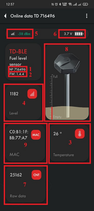
Page "Data" (Android)
-
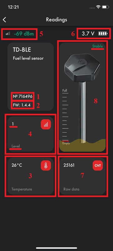
Page "Data" (iOS)


The battery voltage drops to 3.2V for 10-15 seconds - this is normal (especially if this happens after rebooting the sensor by removing the sensor battery and then installing the battery back). This is due to the fact that all processes in the sensor (measuring level, temperature and battery voltage, as well as sending a data packet) are launched simultaneously, thus energy consumption increases, which leads to a temporary decrease in battery voltage.
Sensor calibration

CNT. What happens when you calibrate a sensor?
After you have cut or extended the sensor tubes, you should calibrate it, that is, set the new Full and Empty calibration values. You can do this from the Settings menu on the sensor's main screen.

The sensor's raw data - current level or CNT - changes according to how much fuel is inside its tubes.
Then, CNT is compared with the values Empty and Full.
If the tubes are empty and “CNT (1) ≈ calibration value Empty (2)”, level 1 (3) will be displayed.


If the tubes are full and “CNT (1) ≈ calibration value Full (2)”, level 1023 or 4095 (3) will be displayed.


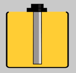
Thus, CNT should increase as the sensor tubes fill with fuel. It should change from a value close to the Empty calibration value to the Full calibration value.
![]()
During sensor calibration, the current CNT is stored as a Full calibration value (if you pressed the Full button) or as an Empty calibration value (if you pressed the Empty button). Calibration values may differ from the current CNT after recording. A difference of ±1000 values is acceptable.
How and why to calibrate sensors?
Initially, the sensor is calibrated to its original length. After you have cut or extended the tubes, you should recalibrate it. Set the new CNT values that the sensor has when its tubes are empty or filled with fuel.
Therefore you should:
- Insert the plastic centralizer provided into the tubes


- Fill the tubes with fuel by covering the drain holes with electrical tape and turning the sensor upside down or immersing the sensor in fuel so that the fuel reaches the flange of the sensor (the drain holes are open). The first method is preferable
-
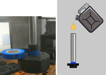
Closing the drain holes, rotating the sensor, and filling the tubes with fuel
-
Filling the tubes by immersing the sensor in fuel (drain holes open)

.png)
- Switch the "Calibration without fuel" slider to the inactive position (1) and press the Full button (2) after the level becomes Stable or the third digit from the end stops changing (for at least 2 minutes) (3)
-
Disable the option "Calibrate without fuel"
-
Click "Full" after the level has stabilized


- Then, drain the fuel from the tubes, wait 2-3 minutes, allowing the fuel to completely drain and the level to stabilize, and press "Empty"

![]()
Calibration without fuel
An alternative calibration method is calibration without fuel.
In this case, make sure that the sensor tubes are empty and there is no fuel in them, but the centralizer must be inserted into the tubes. Leave the "Calibrate without fuel" switch (1) active (green) and press "Calibrate" (2) . The values above the Empty and Full buttons will change automatically.
-
Calibration without fuel
-
Calibration values BEFORE calibration without fuel
-
Calibration values after calibration without fuel


If you calibrate the sensor without fuel, the operating range may change slightly.
There are two measuring ranges:
- From 1 to 1023
- From 1 to 4095
Sensor does not sends level 0. If there is no fuel, level 1 is level sent.
The sensor itself does not know what fuel will be used, so when calibrating without fuel the "Empty" value is set based on the current (CNT), the "Full" value is set by a formula and, depending on the length of the tubes and the final fuel used, the range may change .
For example, when the tank is full, the sensor will show 3843 instead of 4095, or it is possible that when the tank is 98% full, the sensor will already display the value 4095.
If possible, we recommend calibration with fuel. If tank calibration is not planned or is impossible, then calibration with fuel is a mandatory procedure.
When and how to choose a range - 1023 or 4095?
The measuring range 1...1023 is generally recommended for sensors shorter than 500 mm. The measurement range 1...4095 is recommended in other cases.
To change the range, open the Settings menu and select one of two options from the "Maximum Level" drop-down menu (1). After this, click on the “Set parameters” button (2).


How to check if the calibration is correct?
The Empty calibration value must be at least 1.4 (after rounding) less than the Full calibration value.

Preparing the Tank and Sensor
Preparing the Tank
To prepare the tank you should:
- Empty the tank, clean and dry if necessary
- Remove fuel vapors and air from the tank (especially for a gasoline tank, but in the case of a diesel engine, this procedure should not be neglected, since gasoline could be added to the diesel); to do this, you can heat water to boiling point and direct the resulting steam into the tank or use carbon dioxide so that it displaces fuel vapors and air; ensure that any open flame sources are sufficiently far away from the fuel tank
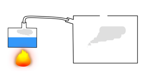
- Find the geometric center of the tank and drill a hole in it using a ø3mm drill bit. Then, using a piece of stiff wire, examine the tank for the presence of partitions in it
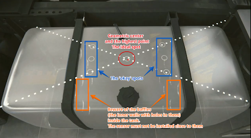
Choosing a location for installing the FLS 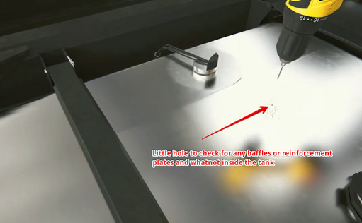
Drilling the tank and subsequent examination of the tank for the presence of partitions - If the space inside the tank in the selected location is free, drill a ø 35 mm hole using a bimetallic bit; When drilling, keep the bit tilted slightly to prevent the cut section from falling into the tank. Use a magnet to catch chips and prevent them from getting into the tank.
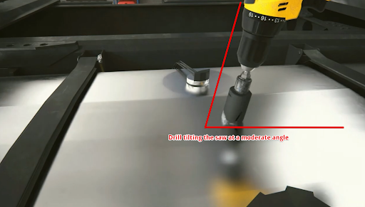
Drilling a hole at an angle 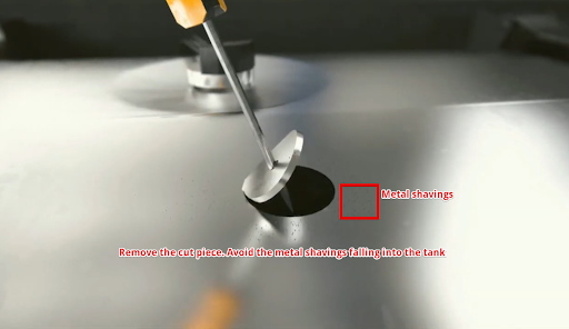
Removing a drilled disc - If it is impossible to install the sensor in the geometric center of the tank, try choosing another location as close as possible to the geometric center of the tank; this point should coincide with the place where the height of the tank is maximum. This way you reduce the risk and amplitude of level fluctuations associated with fuel movement while driving.


Why should the sensor be mounted in the geometric center of the tank?
The highest point must be chosen so that the sensor can measure the level of all the fuel inside the tank without any blind spots.
The fuel level readings from a sensor installed in the center of the tank will be least affected by movement and fuel overflow in the tank.
If it is not possible to install the sensor in the center of the tank, consider installing two sensors diagonally at two corners. When fuel flows to one side of the tank, the level on the corresponding sensor will rise, and on the opposite side, the level will correspondingly decrease, while the average level will remain unchanged.
Video example of the importance of installing the sensor at the geometric center of the tank.

Attention: Before starting the calibration, the vehicle/fuel tank must be positioned flat in relation to the horizon, i.e. on a level surface without a slope.
If the tank has an irregular geometric shape, the sensor must be installed at the maximum depth of the tank, closer to the geometric center.


When installation in the center is impossible - two or more FLS.
To increase accuracy and reduce level fluctuations, install two sensors in one tank. This solution is mainly used in tanks with a capacity of more than 600 liters and having a length of 1500 mm. Sensors must not be installed close to the walls of the tank.
Also, two or more sensors should be installed if it is not possible to install the sensor in the center of the tank and (or) the tank has an elongated shape, i.e. The length of the tank is significantly greater than its height.

Note. Installing a single sensor in an elongated tank will allow you to detect drains and refills. But increased level fluctuations while driving may not allow the monitoring platform to correctly read fuel consumption. Therefore, installing two sensors is preferable.
Installation locations in tanks of complex shapes
Saddle-Style Fuel Tanks
In this case, it is desirable to install two fuel level sensors in the deepest places along the geometric center of the depressions.


Cylindrical tank
In this case, the sensor must be installed in the geometric center of the tank.


Long cylindrical tank
In the case of elongated cylindrical tanks, to improve readings while driving, it is necessary to install two sensors at an equal distance from the geometric center of the tank.


Ladder shape tank
If there is a difference in height in the tank and there is no common bed, it may be necessary to install two fuel level sensors.


Ladder shape tank's tank calibration
When calibrating, it is necessary to create two tables, one for "FLS 1" and the second for "FLS 2"
Let's assume that the calibration step is 10 liters.
At the beginning of calibration, when the fuel is in the "Red Zone", the level changes will only occur on "FLS 2", so we directly add calibration steps of 10 liters to the table for "FLS 2".
When the fuel is in the "Yellow Zone" changes will occur on both "FLS 1" and "FLS 2", during this period we record changes in both tables with half a step, that is, we also fill in 10 liters, but we record 5 liters in the table of each sensor.
When the fuel is in the "Green Zone" the changes will only occur on "FLS 1" so we directly add calibration steps of 10 liters to the table for "FLS 1".
On the platform "FLS 1" and "FLS 2" are started as separate sensors with their own tables and then a third virtual sensor is created with the sum of liters for two sensors, an example of starting two FLS on the platform is shown in this instruction.

Preparing the sensor
Preparing the sensor tubes
Before calibrating the sensor, you should determine the future length of the measuring tubes in accordance with the height of the tank and cut or extend them. The length of the tubes should be calculated according to the following formula:
L = H - 15 mm,
where L - tubes length after changing the length
and
H - height of the tank at the installation point.
ATTENTION!!! The minimum length of the tubes should not be less than 15 cm (150 mm). Otherwise, it will most likely not be possible to obtain adequate graphics. The maximum length of the tubes can reach 6m.


Use a hacksaw to cut the tubes. When sawing, be careful not to damage the connection of the tubes to the circuit board inside the sensor head and to prevent metal shavings from falling into the tubes.

Avoid getting shavings inside the tubes - this may lead to a short circuit in the sensor; if this happens, blow the tubes with compressed air through the drainage holes under the sensor flange. Sand the edges of the tubes with sandpaper to remove any burrs or irregularities.
You can use collet extension and an additional tube. to extend tubes length.
It is not reccomended to use more than one collect extension.

Inner nuts (yellow elements) are used to connect the inner tubes. Once they are installed and the studs are screwed into them, the tubes do not have to touch each other, but try to get them as close to each other as possible..

The outer coupling and the corresponding nuts must be securely tightened. The outer tubes should touch each other.

Watch this video on our YouTube channel to see the real-time connection.
Connection dimensions of the TD-BLE of the former design

Connection dimensions of the TD-BLE of the current design


Tank calibration
Once the length sensor has been adjusted to the height of the tank and the sensor has been calibrated, you need to install it in the tank.
Install the sensor into the tank of the installed tube in the previously drilled hole ø 30-35 mm. Make sure the gasket is installed between the sensor and the tank. After this, screw the screws from the installation kit into the previously drilled ø 3mm holes.
-
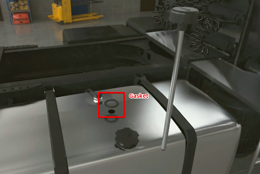
Installing the sensor inside the tank
-
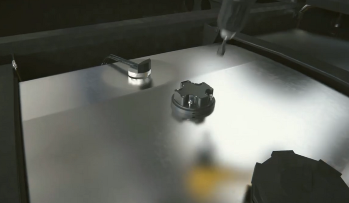
Screwing the self-tapping screws


Proceed to tank calibration. This procedure will result in a "level-liters" (or "level-gallons") table that will allow your monitoring platform to convert the level values that the sensor provides into liters/gallons that are displayed in the monitoring platform reports. You can save the table to the sensor's memory so that the sensor immediately outputs volume values in liters/gallons. You do not need to enter a calibration table on the monitoring platform. The internal memory of the TD BLE sensor can hold up to 50 lines of the calibration table. The capacity of the table on the monitoring platform is usually larger.
In addition, it is easier to change the table or correct errors in the calibration table when it is downloaded to the platform than if the table is stored in the sensor's memory
In order to create such a table, you need to fill the tank by step by step adding fuel to the tank batch by batch and recording level-liter(/gallon) value pairs after each batch using the tank calibration menu in the application.
Suppose you need to calibrate a 100 L tank in ten 10 L portions.
To do this, you should connect the sensor, press the "Tank calibration" (2) button . But before that, in the "Settings" (3) menu , make sure that the filtering level is selected 0 (4). Filtration slows down the level calculation and can increase the tank calibration time.

Then, you can click Start to create a new table, or click Resume to select an existing table from your smartphone memory and continue working with it. If you click Resume, you will need to locate the table file on your Android device that you created/downloaded earlier. Select another folder using the Main Menu button (1) or using the drop-down menu (2). Select the table and click on it (3)
-
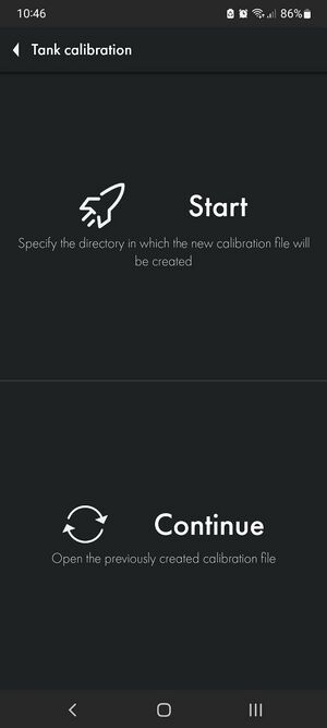
Start or Continue tank calibration
-
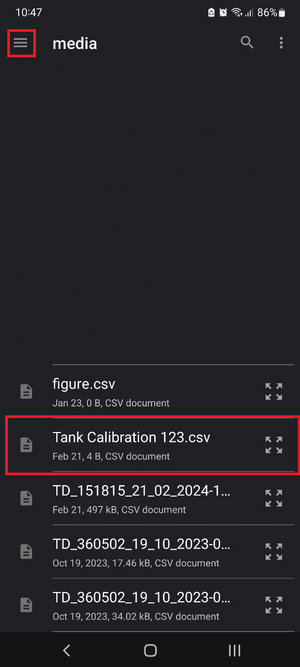
Selecting the tank calibration table file for continuing tank calibration


If you click Start, you will also need to select the folder in which the table will be saved (2) and click the button to select it (3)

Select the calibration type Manual (2).
Mathematical calibration (1) is shown in this article.

Then, you can select the Fill or Drain method (1, 2). The Fill method is recommended as it is more accurate.
If you select the Drain method, you cannot be sure what exact amount of fuel is in the tank and whether the tank is full or not
Next, give the table file a name (3) and set the serving size (4).
ATTENTION! Serving volume is not the number of servings! This is the number of liters/gallons in each serving! In the example below, the tank supposedly contains 100 liters and this volume can be divided into 10 portions of 10 liters. If the volume of the tank was 300L and it needed to be packaged into 10 servings, the serving size would be 30 L.
After this, press Continue (5).
-
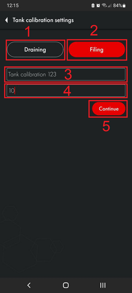
Selection of tank calibration method, table name, portion size
-
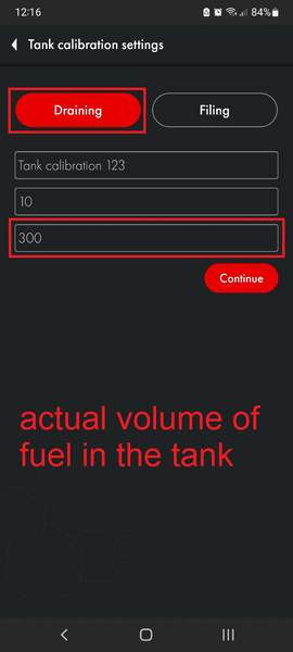
Selection of drain tank calibration method, selection of fuel volume in the tank


After this, you will have a table in which the first line will have 0 liters and level 1. The Calibration mode will also be activated (available in firmware 1.3.3 and later). This means that the sensor starts measuring the level every 5 seconds instead of the usual 10 seconds. It will operate in this mode for the next 30 minutes.
-
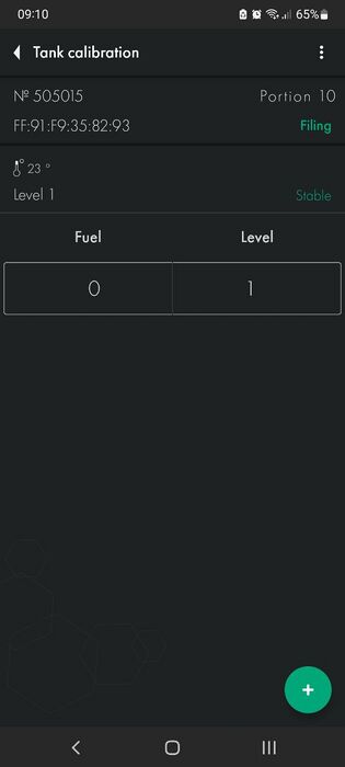
First tank calibration line. 0 liters-gallons and level 1
-
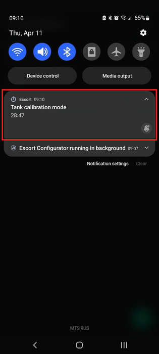
Tank calibration mode timer


If the timer ends before you finish calibrating the tank, you can restart it by saving the table (1, 2), and then, returning to the previous menu (3), click Continue and select the table file. This way you will restart the timer and can continue calibrating the tank in the accelerated level measurement mode. Once you select your file, you will be asked to confirm your previously selected method and serving size.
-

Saving the calibration table and exiting calibration
-
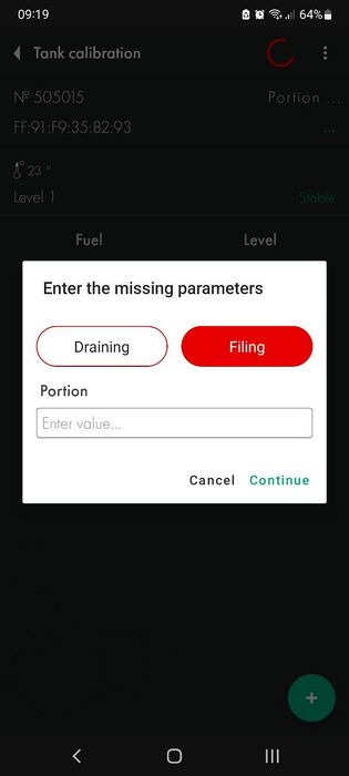
Resuming tank calibration


The table is saved automatically after you click the + button.
Next, you should add the first portion of fuel to the tank. Once the level changes (3) and is displayed as Stable (4), press the + button (1).
In this example, level (3) does not change because during the work on this manual we did not have fuel to carry out a real calibration of the tank. In your case, the level should change (if the fuel touches the tubes) and be Stable before you press the + button.
The following line (2) will appear. The value in the Fuel column will increase according to the Step size (5) you specified when you created the table or when you last modified it (3).
-

Adding the first portion to the tank
-
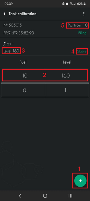
Adding a tank calibration line


You can also change any line by pressing and holding it for some time, after which a dialog box will appear. This way you can correct possible errors.

If you press a line and hold it and swipe left, it will be deleted.

Then, add the next portion of fuel to the tank. Wait for the level to change and stabilize, then press the + button (1). Continue this until the tank is full.
-
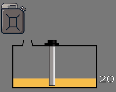
Adding a second portion to the tank
-
Adding a tank calibration line

What to do if it is not possible to completely empty the tank?
If you cannot completely empty the tank, you should somehow calculate the amount of fuel that is in the tank. After this, you can manually edit the table so that it looks like the example below. Or simply edit the table file before you upload it to the monitoring platform.
Let's imagine that there are already 10 liters of fuel in the tank that cannot be removed, so when you place the sensor in the tank, it will immediately begin to show the level of 115, instead of 1.
-
10 liters of fuel in the tank that cannot be removed
-

Calibration table with 10 liters already in the tank

Next, you can add the next portion to the tank. The level value should change. If the level does not change, check the drain holes. They may be blocked by duct tape that you may have used while calibrating the sensor or by pieces of caulk.
If this happens, the air trapped inside the tubes prevents the fuel from rising.
Calibration of tanks with complex shape
If the tank has various curves or other features, you should reduce the size of the portions and increase the number of portions as the fuel rises to the area with the bend or other shape feature. Once the difficult part has been completed, you can return to your original portion size.
Let's imagine that you are calibrating a tank in 10-liter portions. The level rises to areas with complex shapes.


You reduce the portion size from 10 liters to 5. And continue to add fuel portions until the difficult section is completed.

Once the fuel level is above the problem area, you can return to the original portion size of 10 liters.
Once the tank is full, you should have a calibration chart that looks similar to the one shown below.


What to do if the tank cannot be filled completely?
If in your case the level does not reach the maximum range value of 1023 or 4095 due to the fact that the tank cannot be filled completely, do not worry. If your table ends up like the following example, even though the range selected is 1 - 1023, this is acceptable

How many portions should I add
The total number of portions depends on the capacity of the tank. Below is a table with guidelines.
| Recommended number and portion size for calibrating the tank | ||
| Tank volume | Number of portions | Volume of each portion
(Tank Volume / Number of portions) |
| 0-60 | 10-20 | 3-4 |
| 61-100 | 12-20 | 5 |
| 101-500 | 10-50 | 10 |
| 501-1000 | 20-50 | 20 |
| Over a 1000 | As per your capabilities. The rule of thumb is that the larger the portions and smaller the volume, the more accurate the data will be | |
The rule of thumb: more portions means more accurate reports on the monitoring platform.
Calibration of two communicating tanks without the possibility to shut off their communication
First of all it is necessary to check whether it is possible to calibrate both tanks of the vehicle at the same time, because this is the main condition for this kind of calibration. Otherwise, fuel will take a long time to flow into the other tank, which will slow down the process of fuel level stabilization.
Simultaneous tank calibration can be performed either by using 2 smartphones connected to each of these two FLS, or by connecting both sensors to the Base BLE\RS-485 or BA-BLE Base.


Thus, you can do the calibration by pouring portions of fuel into both tanks at the same time.
Tilted tank calibration with 2 FLSs
If it is not possible to level the car/tank with respect to the horizon, you can calibrate it in the tilted position of the tank.
Technically, this kind of calibration is no different from the usual one: you pour a portion of fuel into the tank, wait for the level to stabilize, fix it, and fill in the next portion.
However, the details of such calibration are much more important, so the algorithm of actions should be as follows:
- Pour portions of fuel into the tank until the fuel level reaches the measuring tubes of the second FLS, which is located higher due to the inclination.
- When the second sensor reaches the fuel level, reduce the size of the poured portion by half. IMPORTANT: it is necessary to reduce the portion only in the calibration tables for both FLS; the actual volume of the portion being filled remains unchanged.
- Once the tubes of the sensor located lower down are completely immersed in fuel, the calibration of this FLS is considered complete.
- However, before continuing calibration of the second FLS, it is necessary to return the nominal portion volume to the original (i.e. double it). IMPORTANT: The actual portion size still remains unchanged until the tank is finally filled and the calibration process is completed.
Thus, the resulting calculation tables (calibration tables) will be adequately accepted by the monitoring platform if a third FLS (virtual) is created in it, which is the sum of two real FLS.


Calibration of a tank whose height varies along its length
This method of calibration is in many ways similar to that presented in the previous part.
The algorithm of actions is as follows:
- Pour portions of fuel into the tank until the fuel level reaches the measuring tubes of the second FLS, which is located higher due to the difference in height.
- When the second sensor reaches the fuel level, reduce the size of the poured portion by half. IMPORTANT: it is necessary to reduce the portion only in the calibration tables for both FLS; the actual volume of the portion being filled remains unchanged.
- Continue calibrating in this manner until the tank is full.
Thus, the resulting calculation tables (calibration tables) will be adequately accepted by the monitoring platform if a third FLS (virtual) is created in it, which is the sum of two real FLS.


Mathematical calibration
The mobile application has the ability to create a mathematical calibration table based on the tank size, this functionality is recommended to be used only on large tanks where it is not possible to perform manual calibration by filling/draining.
To create a mathematical calibration, go to the sensor calibration menu (2)

Start calibration and select the file name and storage location in the phone memory and select the mathematical calibration mode.

In the calibration menu, select the type of your tank (1) and fill in the tank size (2), by clicking on the question mark (3) next to the parameter you can call up a hint for this parameter.

Select the range (1) set in the sensor settings (1023 or 4095), Specify the number of portions/calibration lines (2).
After filling in the required fields, click get table (3).

Now you can view and edit the resulting table, by clicking on the three dots (1) you can open a menu in which you can share the table file.

Filtration
After the calibration table is completed, select the filtration level (2) in the Settings menu (1) and click Set parameters (3).


The following are recommendations for selecting a filter level depending on the type of vehicle:
| 0-1 | Stationary objects or tanks |
| 2-4 | Vehicles traveling on smooth paved roads |
| 5-7 | Agricultural machinery |
| 8-10 | Heavy quarry machinery |
These are general recommendations
Basic rules:
- The shorter the sensor (<30cm), the higher the filtration should be set
- The closer the sensor is to one of the tank walls, the higher the filtration must be
- The more rough the road, the higher the filtration should be
Filtration reduces fuel level fluctuations that are caused by fuel splashing while driving.

Sealing and installation
Sensor sealing
Sealing TD-BLE of the former design
To seal the sensor and prevent unauthorized access to the sensor, install the protective cover and thread the seal through the special holes in the cover. Tighten the seal against the end of the seal into the special hole in the seal. Cut off the excess seal wire.

Sealing TD-BLE of the current design
You will need the sensor protective cover and the seal provided in the kit
-
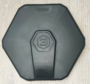
Protective cover TD-BLE
-
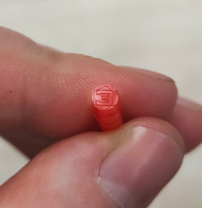
TD-BLE seal


The cover is attached to the sensor head

Then the seal itself is fixed in a special hole (it must be inserted to the end, with the closed end facing outward)
-
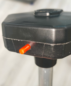
Installing TD-BLE seal
-
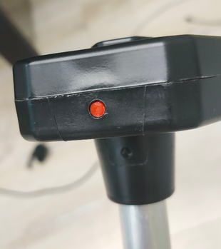
Installed TD-BLE seal


To remove the seal, screw in the special key from the kit (you can also use any self-tapping screw of suitable size) and pull it towards yourself.


This makes it impossible to remove the seal without damaging it. This provides additional protection against unauthorized access.
Alternative sealing for TD-BLE of the current design
Also included with the current TD-BLE is an alternative seal if a numbered seal is required.
- The wire must be threaded through the hole in the sensor cover

- Thread both ends of the cable through the hole in the sensor head

- Pass both ends through the seal, tighten the cable and install the seal by pressing the protruding part of the seal

Tank mounting and transmitter direction
The most common mounting method is self-tapping screws with a sealing washer. It is also possible to install on threaded crimp nuts, welded bushings and other structural elements. The sensor can be mounted on pre-prepared places using screws and bolts with strength class not less than 4.8. It is necessary to ensure tightness of the connection between the sensor body and the tank. For additional protection it is allowed to use automotive oil and gasoline resistant sealant.
For plastic tanks rivets and bolts can be used.

How hard to screw in self-tapping screws

Black box
In order for the black box entries to have an up-to-date time reference, you need to synchronize the black box time with your smartphone time.
The app automatically requests time synchronization if it sees that the black box time is not synchronized.
You can also synchronize the time manually by going to the Advanced settings menu(1) and clicking Synchronize time(2).


To receive data from the Black Box, being in the same Additional tab. Settings, click on the three dots in the upper right corner (1) and select Black Box (2). After this, you can select a period in days (3) and/or hours (4) and download data for the selected one (5) or for the entire period (maximum 30 days) (6). You can also clear the black box by deleting all entries.


Then, click on the Save data button (1). A graph will appear on the screen. On the graph screen, you can also save the upload file to your phone’s memory (2) or send it via instant messengers or email (3).


Also, graphs from the black box can be viewed on a PC using a calibration table through the Escort Charter application
If you have previously saved data from the black box, you can display it by clicking on the graph icon in the upper right corner (1)

Additional settings
In the Additional settings menu, there is an option to disable temperature compensation (1).
ATTENTION! It is not recommended to change the position of the temperature compensation switch (it should remain green) if you do not use your own temperature compensation algorithm.
Data encryption (2) option works only when connecting with RS-485 BLE base or BA-BLE.

Manually setting Full and Empty calibration values
You can skip the sensor calibration step by entering sensor calibration values of the same length manually (1) and pressing the Set button (2).
WARNING!!! Setting the calibration values manually is very likely to increase the error of the sensor. We do not recommend doing this!

Saving a calibration table to the sensor memory
If the calibration table is ready, you can save it to the sensor's memory so that the sensor will output volume values in liters/gallons.
To activate this function, go to the Additional settings menu (1) and press Conversion to liters (2).
This function is not recommended for use if your platform supports the use of a billing table, because to edit the table on the sensor you will need to travel to the sensor, while the table on the platform can be edited remotely at any time.

After that you can activate the conversion to liters or gallons and enter the conversion table manually or by uploading a ready table file.
If the table file is not selected - move it to another folder and try again, it is also desirable that the file name contains only digits
Activate Conversion to liters(1).
To create the table manually, select Level(2) or Liters(3) - in this case it can be any volume unit, enter the value(4) and click on the arrow(5). Then, click on the three dots icon(6) and then click Save to sensor (7).


In order to import a table from the .csv file that you created earlier when calibrating the tank, click on the three dots icon (1), and then click Import from file (2). After that, find the desired file on your smartphone and click on it.
Save the imported table to the sensor (3)

Common problems and solutions
Level does not change
First of all, check if the conversion to liters has not been enabled.
If you did this without saving the table to the sensor’s memory, the sensor will not be able to display either the level or volume in liters.
-
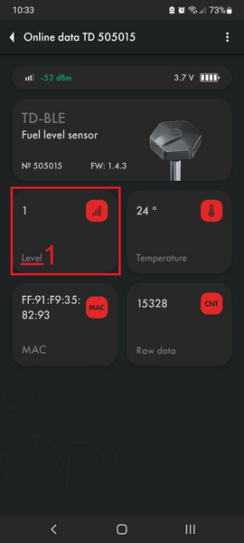
Recalculate in litres is disabled
-

Recalculate in litres is enabled


Another possible reason could be that the sensor has not been properly calibrated and its CNT is below the Empty calibration value. In this case, recalibrate the sensor.
Also, if you calibrated the sensor with fuel, it is possible that the sensor drain holes have remained closed and air trapped inside is preventing fuel from rising through the tubes.
Level 7000
Level 7000 is an error code Short circuit. This indicates that there is dirt, water, chips or other impurities in the tubes. All of these can be highly conductive, while the sensor is designed to work with dielectrics such as fuel.

You should clean the sensor tubes preferably by flushing them with the clean fuel and blowing them through the drain holes with compressed air.
If this error occurred after the start of operation of the sensor, it means that most likely these impurities got into the sensor tubes from the tank and in this case it is also needed to ensure that the tank itself doesn't contain any contaminations. Clean the tank, if necessary. Note that a fuel level sensor installed outside a contaminated tank may function correctly, but the same sensor installed in such a tank may generate this error code.
Level 6500
This code may indicate that the tubes have lost contact. This error code may be generated immediately after cutting the tubes. In this case, simply calibrate the sensor.

If this does not help, check the CNT. If the CNT is below 10,000, it is very likely that the tubes are not in contact with the sensor board.
Take a photo of the sensor head (the sensor serial number should be visible), its tubes (the correspondence or discrepancy of the tubes length should be clearly visible), take a screenshot of the main screen of the sensor and the Settings menu page in the application and send these data to tech support.
Sensor is not connected or detected in the application
First of all, check that the sensor is not connected to other devices. It can only be connected to one device at a time.
Then make sure Geolocation (Location) is enabled and the app has access to it.
Check if the sensor is detected in the nRF Connect application.

If the sensor is detected, but the Escort configurator application does not see it, try connecting to other sensors in the application using the same smartphone.
Then, try loosening the screws securing the sensor to the tank.
If the sensor is still not detected or cannot be connected, open the cover and remove the battery. Check the voltage with a multimeter. If it is 3.2 V or higher, reinsert the battery and try to connect again.

If none of the above helps, we recommend contacting our tech support.
Loss of communication with the tracker or error codes 65530, 0, 65532, -4
The most common cause of communication loss is low signal strength between the tracker and the sensor.
It is recommended to measure the average signal strength at the tracker (RSSI) during installation. A good signal strength is considered to be between -35 dBm and -85 dBm.
If the signal strength is lower than optimal, it can be improved by pointing the sensor antenna towards the receiving device.
The main factor that affects the strength of signal reception is obstacles. Therefore, it is important to place the tracker in a location with as few obstacles as possible between it and the sensor.
If you cannot improve the signal quality of the tracker, you can use RS-485 BLE base or BA-BLE.With a base station, the signal should become more stable. If necessary, the base can be placed in a remote location away from the tracker where there is less obstruction to the signal, or it can be moved outside the cabin, as the base motherboard is protected with compound and has wind and moisture protection.
You can unload the data from the black box to check if there is data transmission from the sensor during moments of communication loss.
Tracker Communication Error Codes
65530 - error code of Navtelecom trackers, it means loss of connection.
Some of the trackers can send 0 in the fuel level parameter as a loss of communication error code, the sensor can only send values 1-4095 and error codes 7000 and 6500.
Teltonika trackers can send 0 in the level parameter and -4\65532 in the temperature parameter as a loss of communication error code.
Firmware update (FW)

To update the firmware on the TD-BLE:
- Download the current firmware version as a file to the phone memory
- Connect to the sensor
- Go to “Additional Features”
- Go to FW update

- Select the firmware file (1) from the phone memory (The firmware file is the .zip archive itself, no need to unzip it) and start the flashing process (2). These actions should be performed within 30 seconds after entering update mode!

- The flashing process should start. Do not close or minimize the application during the flashing process!

- When the updating is completed, a window will pop up indicating that the update was successful

Firmware update via the IOS mobile application is shown in this video
Up-to-date firmware can be found in the download section.
The firmware file is the .zip archive itself, no need to unzip.
How to change the battery
The sensors use two types of batteries SAFT LS14500 and SAFT LS17500 with capacities of 2.6Ah and 3.6Ah respectively.
The average consumption of the TD-BLE sensor is 42.5 µA.

Replacing the battery in the current design of TD-BLE
Remove the sensor's protective cover using a screwdriver or other thin object.

Remove the cover from the battery holder by unscrewing the screws holding it in place.

Carefully remove the top layer of lithol using a thin, non-sharp object.

Remove the battery. When replacing the battery, please note that the current TD-BLE may use a battery model that is different from the one that corresponds to the previous sensor housing; namely: Saft LS17500 (ordered as a separate option).
After you have replaced the battery and checked the functionality of the sensor using a mobile application, the holder with the battery inside should also be filled with lithol.
Replacing the battery in the older design of TD-BLE
Example using a battery replacement kit
- Remove the cover from the fuel sensor by unscrewing the 8 screws.
- Remove the power source (battery) from the sensor body by carefully cutting it out of the transparent compound using a knife. (Damage to the printed circuit board and cutting of wires on the board are not allowed).


- Clean the sensor contacts from grease and remove any remaining compound.

- Install a new power source (battery) into the sensor housing and check the functionality and voltage of the power source. (Must be at least 3.4V).
- Remove the new power supply from the housing. Apply a thin layer of lithol lubricant using a syringe to two contacts. The lubricant should not get onto the center of the contact (Lithol lubricant serves as a barrier and protects against the compound flowing onto conductive contacts).

- Install the power supply into the sensor housing. Check functionality.
- Apply a thin layer of lithol lubricant over the contacts.

- Preparing the compound for filling the power source. To do this, you need to: - open the jar with component A (Fig. 5) and the bottle with component B (Fig. 6) - pour the contents of the bottle with component B into the jar with component A; - mix the two components for at least 2 minutes;

- Fill the power source with compound at the same level as the previous layer of compound, then leave it in the open air for at least 15 minutes. Do not leave areas of the power source unflooded! Bubbles are allowed in the pouring area.

- Check the functionality of the sensor.
- Install the cover and tighten the 8 screws. Operation can begin after 4 hours. The maximum strength of the silicone elastomer is achieved after 24 hours.
If the replacement is made without using a repair kit, it is also necessary to lubricate the contacts with lithol, it should be available for purchase in publicly accessible electronics/tool stores or online stores like Litol-24.
Instead of a 2-component compound, you can use oil-gasoline-resistant sealants that are neutral in acidity (on an acetic-free base)
Examples of sealants recommended by the community

