[[Файл:TD-150.png|мини|'''<big>Текущий дизаин ТД-150</big>''']]High-precision fuel level sensors (FLS, also meters or sensors) of the Escort brand are designed to determine the filling level of petroleum products in fuel tanks, reservoirs and storage tanks. The TD-150 meter (sensor) is used in transport technology as a fuel level meter, in industry - as a level meter for any light petroleum products. Escort FLS measurement type is capacitive. Its readings are based on the dielectric constant of the medium in which it operates; in this case, the medium is various types of light petroleum products (gasoline, diesel, kerosene, motor oil).
[[File:TD-150.png|thumb|'''<big>Current design of TD-150</big>''']]
High-precision fuel level sensors (FLS, also meters or sensors) of the Escort brand are designed to determine the filling level of petroleum products in fuel tanks, reservoirs and storage tanks. The TD-150 meter (sensor) is used in transport technology as a fuel level meter, in industry - as a level meter for any light petroleum products. Escort FLS measurement type is capacitive. Its readings are based on the dielectric constant of the medium in which it operates; in this case, the medium is various types of light petroleum products (gasoline, diesel, kerosene, motor oil).
More detailed technical characteristics are presented in the [https://www.fmeter.ru/download/_ftp/datchik-urovnja-topliva/eskort-td-150/%D0%9F%D0%B0%D1%81%D0%BF%D0%BE%D1%80%D1%82_%D0%A2%D0%94-150.pdf?v=271022141709 technical data sheet of the device.]
More detailed technical characteristics are presented in the [https://www.fmeter.ru/download/_ftp/datchik-urovnja-topliva/eskort-td-150/%D0%9F%D0%B0%D1%81%D0%BF%D0%BE%D1%80%D1%82_%D0%A2%D0%94-150.pdf?v=271022141709 technical data sheet of the device.]
Line 23:
Line 24:
'''''Interface''''' - a physical connection method and/or a set of software tools that allows data to be transferred between two or more devices.
'''''Interface''''' - a physical connection method and/or a set of software tools that allows data to be transferred between two or more devices.
'''''RS-485''''' - digital data transmission mode. The sensor waits for a corresponding request from the receiving device. Works using the LLS protocol. Based on CNT, a value is generated in conventional units of the selected range (1-1023 cu or 1-4095 cu)
'''''RS-485''''' - digital data transmission mode. The sensor waits for a corresponding request from the receiving device. Works using the LLS protocol. Based on CNT, a value is generated in conventional units of the selected range (1-1023 units or 1-4095 units)
'''''Converter''''' - digital converter RS-485 to USB ([https://www.fmeter.ru/download/_ftp/escort_c-200m/%D0%9F%D0%B0%D1%81%D0%BF%D0%BE%D1%80%D1%82%20%D0%A1-200%D0%9C.pdf?v=200320145441 С200М] или [https://www.fmeter.ru/download/_ftp/escort_c-200m/%D0%9F%D0%B0%D1%81%D0%BF%D0%BE%D1%80%D1%82%20%D0%A1-200M2.pdf?v=150323104901 С200М2]) for configuring wired sensors.
'''''Converter''''' - digital converter RS-485 to USB ([https://www.fmeter.ru/download/_ftp/escort_c-200m/%D0%9F%D0%B0%D1%81%D0%BF%D0%BE%D1%80%D1%82%20%D0%A1-200%D0%9C.pdf?v=200320145441 С200М] или [https://www.fmeter.ru/download/_ftp/eng/escort_c-200m/Datasheet%20Escort%20C-200M2.pdf?v=050623134318 С200М2]) for configuring wired sensors.
'''''Active (periodic) RS-485''''' - operating mode in which the sensor, without waiting for a request from the receiver, itself transmits packets with command data within 2 seconds.
'''''Active (periodic) RS-485''''' - operating mode in which the sensor, without waiting for a request from the receiver, itself transmits packets with command data within 2 seconds.
Line 33:
Line 34:
'''''Frequency''''' - mode in which the corresponding frequency in Hz is generated based on the CNT (301-1323 Hz with a value range of 1-1023; 301-4395 Hz with a value range of 1-4095).
'''''Frequency''''' - mode in which the corresponding frequency in Hz is generated based on the CNT (301-1323 Hz with a value range of 1-1023; 301-4395 Hz with a value range of 1-4095).
'''''Navigation terminal''''' - the main element of the system for monitoring the operation of transportation carried out by means of satellite communication. Without it, it is impossible to control transportation, to determine the coordinates of the vehicle location. It collects information from sensors and on-board system of the vehicle, and then transmits it to the device/server, which belong to the controlling specialist.
'''''GPS tracker''''' - the main element of the system for monitoring the operation of transportation carried out by means of satellite communication. Without it, it is impossible to control transportation, to determine the coordinates of the vehicle location. It collects information from sensors and on-board system of the vehicle, and then transmits it to the device/server, which belong to the controlling specialist.
= '''<big>Preparation</big>''' =
= '''<big>Preparation</big>''' =
Line 41:
Line 42:
* Empty the tank, clean and dry if necessary
* Empty the tank, clean and dry if necessary
* '''Remove fuel vapors and air from the tank''' (especially for a gasoline tank, but in the case of a diesel engine, this procedure should not be neglected, since gasoline could be added to the diesel); to do this, you can heat water to boiling point and direct the resulting steam into the tank or use carbon dioxide so that it displaces fuel vapors and air; ensure that any open flame sources are sufficiently far away from the fuel tank
* '''Remove fuel vapors and air from the tank''' (especially for a gasoline tank, but in the case of a diesel engine, this procedure should not be neglected, since gasoline could be added to the diesel); to do this, you can heat water to boiling point and direct the resulting steam into the tank or use carbon dioxide so that it displaces fuel vapors and air; ensure that any open flame sources are sufficiently far away from the fuel tank[[File:Removing fuel vapors.png|frameless|787x787px]]
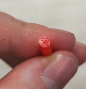
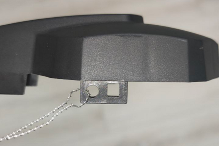
* '''Find the geometric center of the tank and drill a hole''' in it using a '''ø3mm''' drill bit. Then, using a piece of stiff wire, examine the tank for the presence of partitions in it
* [[File:Choosing a location for installing the FLS.png|none|thumb|512x512px|'''<big>Choosing a location for installing the FLS</big>''']][[File:Little hole drilling.png|none|thumb|512x512px|'''<big>Drilling the tank and subsequent examination of the tank for the presence of partitions</big>''']][[File:Angled drilling.png|none|thumb|512x512px|'''<big>Drilling a hole at an angle</big>''']][[File:Removing metal part.png|none|thumb|512x512px|'''<big>Removing a Drilled Disc</big>''']]If the space inside the tank in the selected location is free, '''drill a ø 35 mm hole''' using a bimetallic bit; When drilling, keep the bit tilted slightly to prevent the cut section from falling into the tank. Use a magnet to catch chips and prevent them from getting into the tank.
* '''Find the geometric center of the tank and drill a hole''' in it using a '''ø3mm''' drill bit. Then, using a piece of stiff wire, examine the tank for the presence of partitions in it[[Файл:Выбор места установки ДУТ.png|без|мини|831x831пкс|'''<big>Выбор места установки ДУТ</big>''']][[Файл:Сверление бака и последующее исследование бака на наличие перегородок.png|без|мини|835x835пкс|'''<big>Сверление бака и последующее исследование бака на наличие перегородок</big>''']]
* If the space inside the tank in the selected location is free, '''drill a ø 35 mm hole''' using a bimetallic bit; When drilling, keep the bit tilted slightly to prevent the cut section from falling into the tank. Use a magnet to catch chips and prevent them from getting into the tank.[[Файл:Сверление отверстия под углом.png|без|мини|714x714пкс|'''<big>Сверление отверстия под углом</big>''']][[Файл:Удаление высверленного диска.png|без|мини|864x864пкс|'''<big>Удаление высверленного диска</big>''']]
* If it is impossible to install the sensor in the geometric center of the tank, try choosing another location as close as possible to the geometric center of the tank; this point should coincide with the place where the height of the tank is maximum. This way you reduce the risk and amplitude of level fluctuations associated with fuel movement while driving.
* If it is impossible to install the sensor in the geometric center of the tank, try choosing another location as close as possible to the geometric center of the tank; this point should coincide with the place where the height of the tank is maximum. This way you reduce the risk and amplitude of level fluctuations associated with fuel movement while driving.
Line 55:
Line 54:
If it is not possible to install the sensor in the center of the tank, consider installing two sensors diagonally at two corners. When fuel flows to one side of the tank, the level on the corresponding sensor will rise, and on the opposite side, the level will correspondingly decrease, while the average level will remain unchanged.
If it is not possible to install the sensor in the center of the tank, consider installing two sensors diagonally at two corners. When fuel flows to one side of the tank, the level on the corresponding sensor will rise, and on the opposite side, the level will correspondingly decrease, while the average level will remain unchanged.
[https://youtu.be/3psA2ACmw7w?si=zQ7n_N6h0HseNdfF Видео пример важности установки датчика по геометрическому центру бака.]
[https://www.youtube.com/watch?v=T0Pd6TOpuc8&ab_channel=EscortSensors Video example of the importance of installing the sensor at the geometric center of the tank.]
[[Файл:Положение датчика и перетекание топлива.png|без|мини|805x805px|<big>'''Положение датчика и перетекание топлива'''</big>]]
[[File:Sensor position and fuel flow.png|none|thumb|512x512px|'''<big>Sensor position and fuel flow</big>''']]
<blockquote>'''Attention:''' Before starting the calibration, the vehicle/fuel tank must be positioned flat in relation to the horizon, i.e. on a level surface without a slope.</blockquote>If the tank has an irregular geometric shape, the sensor must be installed at the maximum depth of the tank, closer to the geometric center.
<blockquote>'''Attention:''' Before starting the calibration, the vehicle/fuel tank must be positioned flat in relation to the horizon, i.e. on a level surface without a slope.</blockquote>If the tank has an irregular geometric shape, the sensor must be installed at the maximum depth of the tank, closer to the geometric center.
[[Файл:Датчик установлен в самое высокое место бака..png|без|мини|737x737пкс|'''<big>Датчик установлен в самое высокое место бака</big>''']]
[[File:The sensor is installed in the highest place of the tank.png|none|thumb|874x874px|'''<big>The sensor is installed in the highest place of the tank</big>''']][[File:Ladder tank.png|frameless|470x470px]]
[[File:Ladder tank I.png|frameless|451x451px]]
==== '''<big>When installation in the center is impossible - two or more FLS.</big>''' ====
==== '''<big>When installation in the center is impossible - two or more FLS.</big>''' ====
Line 64:
Line 65:
Also, two or more sensors should be installed if it is not possible to install the sensor in the center of the tank and (or) the tank has an elongated shape, i.e. The length of the tank is significantly greater than its height.
Also, two or more sensors should be installed if it is not possible to install the sensor in the center of the tank and (or) the tank has an elongated shape, i.e. The length of the tank is significantly greater than its height.
[[Файл:Два датчика установленных по диагонали.png|без|мини|748x748пкс|'''<big>Два датчика установленных по диагонали</big>''']]
'''Note.''' Installing a single sensor in an elongated tank will allow you to detect drains and refills. But increased level fluctuations while driving may not allow the monitoring platform to correctly read fuel consumption. Therefore, installing two sensors is preferable.
'''Note.''' Installing a single sensor in an elongated tank will allow you to detect drains and refills. But increased level fluctuations while driving may not allow the monitoring platform to correctly read fuel consumption. Therefore, installing two sensors is preferable.
== '''<big><u>Installation locations in tanks of complex shapes</u></big>''' ==
=== '''<big>Saddle-Style Fuel Tanks</big>''' ===
In this case, it is desirable to install two fuel level sensors in the deepest places along the geometric center of the depressions.
[[File:Saddle shape.png|frameless|749x749px]]
[[File:Saddle shape top view.png|frameless|749x749px]]
[[File:Saddle shape side view.png|frameless|749x749px]]
=== '''<big>Cylindrical tank</big>''' ===
In this case, the sensor must be installed in the geometric center of the tank.
[[File:Cylindrical tank.png|frameless|750x750px]]
[[File:Cylindrical tank top view.png|frameless|750x750px]]
[[File:Cylindrical tank inside view.png|frameless|750x750px]]
==== '''<big>Long cylindrical tank</big>''' ====
In the case of elongated cylindrical tanks, to improve readings while driving, it is necessary to install two sensors at an equal distance from the geometric center of the tank.
[[File:Cylindrical tank long.png|frameless|750x750px]]
[[File:Cylindrical tank long inside view.png|frameless|750x750px]]
==== '''<big>Ladder shape tank</big>''' ====
If there is a difference in height in the tank and there is no common bed, it may be necessary to install two fuel level sensors.
[[File:Ladder 2 tank.png|frameless|782x782px]]
[[File:Ladder 2 tank inside view.png|frameless|750x750px]]
===== '''<big>Ladder shape tank's tank calibration</big>''' =====
When calibrating, it is necessary to create two tables, one for "'''FLS 1'''" and the second for "'''FLS 2'''"
Let's assume that the calibration step is 10 liters.
At the beginning of calibration, when the fuel is in the "'''Red Zone'''", the level changes will only occur on "'''FLS 2'''", so we directly add calibration steps of 10 liters to the table for "'''FLS 2'''".
When the fuel is in the "'''Yellow Zone'''" changes will occur on both "'''FLS 1'''" and "'''FLS 2'''", during this period we record changes in both tables with half a step, that is, we also fill in 10 liters, but we record 5 liters in the table of each sensor.
When the fuel is in the "'''Green Zone'''" the changes will only occur on "'''FLS 1'''" so we directly add calibration steps of 10 liters to the table for "'''FLS 1'''".
On the platform "'''FLS 1'''" and "'''FLS 2'''" are started as separate sensors with their own tables and then a third virtual sensor is created with the sum of liters for two sensors, an example of starting two FLS on the platform is shown [https://docs.google.com/document/d/14p9GYmY0D1Wjz0ZfJXO-soVfxRBP7EiY7TgibD6vmZQ/edit?usp=sharing in this instruction.]
[[File:Ladder 2 tank calibration.png|frameless|750x750px]]
== '''<big>Preparing the sensor</big>''' ==
== '''<big>Preparing the sensor</big>''' ==
=== '''<big>Preparing the sensor tubes</big>''' ===
=== '''<big>Preparing the sensor tubes</big>''' ===
Перед калибровкой датчика следует '''определить будущую длину''' измерительных трубок в соответствии с высотой бака и '''обрезать или удлинить их'''. Длину трубок следует вычислить в соответствии со следующей формулой:
Before calibrating the sensor, you should '''determine the future length''' of the measuring tubes in accordance with the height of the tank and '''cut or extend them'''. The length of the tubes should be calculated according to the following formula:
'''L = H - 15 mm,'''
'''L = H - 15 мм,'''
where L - tubes length after changing the length
где L - длина трубок после изменения длины
and
и
H - height of the tank at the installation point.<blockquote>'''ATTENTION!!!''' '''The minimum length''' of the tubes should not be less than '''15 cm (150 mm)'''. Otherwise, it will most likely not be possible to obtain adequate graphics. The maximum length of the tubes can reach '''6m.'''</blockquote>
[[File:Measuring height of the tank.png|none|thumb|887x887px|'''<big>Measuring height of the tank</big>''']]
[[File:Measuring tubes length.png|none|thumb|893x893px|'''<big>Measuring the length of tubes</big>''']]
Use a hacksaw to cut the tubes. When sawing, be careful not to damage the connection of the tubes to the circuit board inside the sensor head and to prevent metal shavings from falling into the tubes.
[[File:Cutting the tubes.gif|none|thumb|600x600px|'''<big>Cutting the tubes</big>''']]
H - высота бака в месте установки.<blockquote>'''<big>ВНИМАНИЕ!!!</big> Минимальная длина''' трубок не должна быть меньше '''15 см (150 мм)'''. Иначе получить адекватные графики вероятнее всего не удастся. '''Максимальная длина''' '''трубок''' может достигать '''6м'''.</blockquote>
[[Файл:Измерение высоты бака.png|без|мини|843x843пкс|<big>'''Измерение высоты бака'''</big>]]
[[Файл:Измерение длины трубок.png|без|мини|846x846пкс|'''<big>Измерение длины трубок</big>''']]
Для обрезки трубок используйте ножовку по металлу. Во время отпиливания будьте аккуратны, чтобы не повредить соединение трубок с платой внутри головы датчика и не допустить попадания стружки в трубки.
'''Избегайте попадания стружки внутрь трубок - это может привести к короткому замыканию в датчике, если это произошло - продуйте трубки сжатым воздухом через дренажные отверстия под фланцем датчика.''' Обработайте края трубок при помощи наждачной бумаги для удаления заусенцев и неровностей.
Для удлинения трубок датчика, используйте цанговый удлинитель и дополнительный сегмент трубок.
'''Avoid getting shavings inside the tubes - this may lead to a short circuit in the sensor; if this happens, blow the tubes with compressed air through the drainage holes under the sensor flange.''' Sand the edges of the tubes with sandpaper to remove any burrs or irregularities.
Внутренние гайки (желтые элементы) служат для соединения внутренних трубок. После их установки и вкручивания в них шпильки трубки не обязательно должны касаться друг друга, но постарайтесь подвести их друг к другу так близко, насколько это возможно.
[[Файл:Внутреннее соединение цангового соединения .png|без|мини|621x621пкс|'''<big>Внутреннее соединение цангового соединения</big>''' ]]
Наружная соединительная муфта и соответствующие гайки должны быть надежно затянуты. '''Наружнее трубки должны касаться друг друга'''.
[[Файл:Цанговое соединение установлено.png|без|мини|602x602px|'''<big>Цанговое соединение установлено</big>''']]
[https://www.youtube.com/watch?v=Z0HSGDMR3rQ Посмотрите это видео на нашем YouTube канале для ознакомления с соединением в реальном времени.]
== '''<big>Присоединительные размеры</big>''' ==
To extend sensor tubing, use a collet extension and an additional tube.
[[Файл:Присоединительные размеры проводных дут.png|без|мини|600x600пкс|'''<big>Присоединительные размеры проводных дут</big>''']]
Inner nuts (yellow elements) are used to connect the inner tubes. Once they are installed and the studs are screwed into them, the tubes do not have to touch each other, but try to get them as close to each other as possible.
[[File:Internal connection of the collet connection.png|none|thumb|748x748px|'''<big>Internal connection of the collet connection</big>''']]
The outer coupling and the corresponding nuts must be securely tightened. '''The outer tubes should touch each other.'''
[https://www.youtube.com/watch?v=b_WtOHzKtDM Watch this video on our YouTube channel for a real-time overview of the connection.]
= '''<big>Подключение к датчику, настройка, калибровка и тарировка через [https://www.fmeter.ru/download/_ftp/all/dut/FLS_Configurator.zip?v=210521143455 конфигуратор на ПК]</big>''' =
== '''<big>Connection dimensions</big>''' ==
[[File:Dimenstions TD 150.png|none|thumb|702x702px|'''<big>Connection dimensions of the wired FLS</big>''']]
== '''<big>Установка конфигуратора и подключение к датчику</big>''' ==
= '''<big>Connection to the sensor, setup, calibration and calibration via [https://www.fmeter.ru/download/_ftp/all/dut/FLS_Configurator.zip?v=210521143455 the configurator on a PC]</big>''' =
Датчик можно настроить при помощи [https://www.fmeter.ru/download/_ftp/all/dut/FLS_Configurator.zip?v=210521143455 '''<big>конфигуратора на ПК</big>'''] (далее - "'''конфигуратор'''").
'''Подключите датчик к преобразователю USB-RS-485 при помощи 6-ти пинового MOLEX разъема''' или при помощи кабельных зажимов, если к датчику подключена кабель-трасса). Оранжевый провод - линия А RS-485 интерфейса датчика, белый провод - линия В RS-485 интерфейса датчика, черный провод - GND, красный - PWR.
== '''<big>Installation of the configurator and connection to the sensor</big>''' ==
[[Файл:Датчик подключенный при помощи MOLEX.png|без|мини|800x800пкс|'''<big>Датчик подключенный при помощи MOLEX</big>''']]
The sensor can be configured using [https://www.fmeter.ru/download/_ftp/all/dut/FLS_Configurator.zip?v=210521143455 '''<big>the configurator on a PC</big>'''] (From here onwards- "'''configurator'''").
[[Файл:Датчик подключенный при помощи кабель-трассы (укороченной) и кабельных зажимов.png|без|мини|800x800пкс|'''<big>Датчик подключенный при помощи кабель-трассы (укороченной) и кабельных зажимов</big>''']]
Мы рекомендуем использовать преобразователь USB-RS-485 Escort C200M/C200М2 нашего производства, так как мы не можем гарантировать 100% совместимость наших устройства с преобразователями других брендов.
При работе с ноутбуком, рекомендуем подключить его к сети питания и/или подключить дополнительный USB кабель в разъем ADD PWR C200M. В ином случае может не хватить питания для работы датчика и преобразователя.
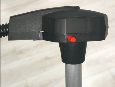
'''Connect the sensor to the USB-RS-485 converter using a 6-pin MOLEX connector''' or using cable clamps if a cable route is connected to the sensor. Orange wire is line A of the RS-485 sensor interface, white wire is line B of the RS-485 sensor interface, black wire is GND, red is PWR.
[[File:Sensor connected via MOLEX.png|none|thumb|731x731px|'''<big>Sensor connected via MOLEX</big>''']]
[[File:Sensor connected via cables and cable clamps.png|none|thumb|731x731px|'''<big>Sensor connected via cables and cable clamps</big>''']]
We recommend using our Escort C200M/C200M2 USB-RS-485 converter, since we cannot guarantee 100% compatibility of our devices with converters from other brands.
Вместе с установкой конфигуратора 1.0.2.38 драйвера на С200М установятся автоматически.
When working with a laptop, we recommend connecting it to the power supply and/or connecting an additional USB cable to the ADD connector of the PWR C200M. Otherwise, there may not be enough power to operate the sensor and transmitter.
Если вы используете С200М2 на операционных системах windows 10 и 11 драйвера должны установиться автоматически из центра обновления windows, на операционной системе windows 7 и ниже может понадобится [https://remontka.pro/disable-drivers-signature-check-windows-10/ отключение электронной подписи драйверов] и ручная установка [https://www.fmeter.ru/download/_ftp/escort_c-200m/%D0%94%D1%80%D0%B0%D0%B9%D0%B2%D0%B5%D1%80%20%D0%B4%D0%BB%D1%8F%20C-200M2.zip?v=150323104902 драйверов на С200М2].
Along with installing the configurator 1.0.2.38, the drivers for the C200M will be installed automatically.
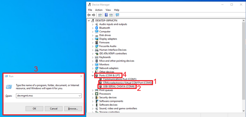
Если драйвер был верно установлен, то после подключение преобразователя к вашему ПК/ноутбуку, вы увидите устройство STMicroelectronics Virtual COM Port ('''1''')(С200М) или USB-SERIAL CH341A ('''2''')(C200М2) в пункте COM и LPT порты диспетчера устройства Windows "для входа в данное меню нажмите '''win+r''' и введите '''devmgmt.msc''' и нажмите '''ОК'''('''3''') и после раскройте подменю ком портов ('''4''')"
If you use C200M2 on Windows 10 and 11 operating systems, drivers should be installed automatically from Windows Update, on the Windows 7 operating system and below, you may need to [https://windowsreport.com/driver-signature-enforcement-windows-10/ disable the electronic signature of drivers] and manually install [https://www.fmeter.ru/download/_ftp/eng/escort_c-200m/Escort%20driver%20C-200M2.zip?v=050623134319 drivers for the С200M2].
Номер ком порта отобрадаемый в данном меню так же нужнен для подключения датчика.
If the driver was installed correctly, then after connecting the converter to your PC/laptop, you will see the STMicroelectronics Virtual COM Port ('''1''')(C200M) or USB-SERIAL CH341A ('''2''')(C200M2) device in the COM and LPT ports section of the Windows device manager " to enter this menu, press '''win+r''' and enter '''devmgmt.msc''' and press '''OK''' ('''3''') and then expand the com ports submenu ('''4''')"
[[Файл:Ком порты С200М и С200М2.png|900x900пкс]]
The com port number displayed in this menu is also needed to connect the sensor.
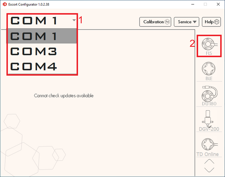
После подключения преобразователя, датчика к нему и проверки установки драйверов с проверкой номера ком порта преобразователя необходимо открыть конфигуратор, выбрать нужный ком порт который мы могли узнать в диспетчере устройств('''1''') и нажать кнопку '''ДУТ''' ('''2''').
[[Файл:Выбор ком порта и ДУТ.png|750x750пкс]]<blockquote>Подключение к дут следует сделать '''в течении 15 сек после того''', как датчик был подключен к питанию, если режим работы датчика был изменен с RS-485 на любой другой. </blockquote>После подключения датчика вы должны увидеть это меню:
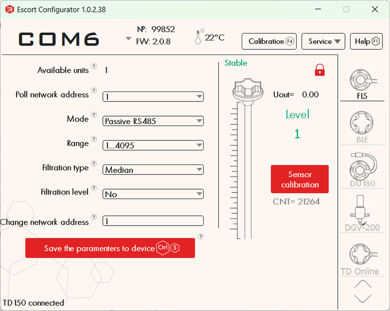
After connecting the converter, sensor to it and checking the installation of drivers by checking the com port number of the converter, you need to open the configurator, select the desired com port which we could find in the device manager ('''1''') and press the '''FLS''' button ('''2''').
[[Файл:Описание основного меню конфигуратора на ПК, проводного дут .png]]
[[File:Com ports selection.png|frameless|657x657px]]<blockquote>The connection to the FLS should be made '''within 15 seconds after the sensor has been connected''' to power, if the sensor operating mode has been changed from RS-485 to any other. </blockquote>After connecting the sensor you should see this menu:
# Серийный номер датчика
[[File:Main page PC configurator.png|frameless|751x751px]]
# Версия прошивки датчика (FW)
# Температура датчика
# Текущий уровень датчика
# Текущий уровень CNT (необработанное значение уровня) датчика
# Сетевые адреса LLS подключенные к данному преобразователю (если в данном списке больше одного адреса значит либо в линию одновременно подключено больше одного датчика либо на линии имеются помехи, в таком случае необходимо проверить подключение к дут на наличие других конфликтующих устройств и необходимо закрыть другие программы использующие ком порты например конфигуратор трекера)
# Сетевой адрес опрашиваемого датчика (Этот адрес используется при подключении в режиме RS485)
# Текущий режим работы датчика
# Текущий диапзаон выдаваемых значений (1-1023 или 1-4095)
# Текущий тип фильтрации и степень
# Модель подключенного датчика
== '''<big>Калибровка датчика</big>''' ==
# Sensor serial number
[[Файл:Калибровка дут на ПК.gif]]
# Sensor firmware version (FW)
# Sensor temperature
# Current sensor level
# Current CNT level (raw level value) of the sensor
# LLS network addresses connected to this converter (if there is more than one address in this list, it means either more than one sensor is connected to the line at the same time or there is interference on the line, in this case it is necessary to check the connection to the FLS for the presence of other conflicting devices and it is necessary to close other programs using the com ports for example tracker configurator)
# Network address of the polled sensor (This address is used when connecting in RS485 mode)
# Current sensor operating mode
# Current range of output values (1-1023 or 1-4095)
# Current filtration type and degree
# Connected sensor model
После того, как вы удлинили или укоротили трубки датчика - необходимо провести процедуру калибровки датчика.
* Наполните трубки топливом (заклеив дренажные отверстия изолентой и наполнив трубки перевернув датчик или погрузив трубки датчика полностью в топливо)
* Дождитесь стабилизации уровня CNT ('''1''')
* Уберите выделение с ползунка "'''Калибровка без топлива'''" ('''2''')
* Нажмите "'''Полный'''" ('''3''')
* Значение "'''Полный'''"('''4''') должно измениться на значение близкое к значению текущего CNT ('''1'''), но не равно ему, так как данное значение задается согласно термокомпенсации датчика
* Fill the tubes with fuel (by sealing the drain holes with duct tape and filling the tubes, turning the sensor upside down, or submerging the sensor tubes completely in fuel)
[[Файл:Центратор_на_трубках.png|без|мини|670x670пкс|'''<big>Центратор на трубках</big>''']]
* Wait for the CNT level to stabilize ('''1''')
* Deselect the '''"Calibration without fuel'''" slider ('''2''')
* Click '''"Full"''' ('''3''')
* The value '''"Full"''' ('''4''') should change to a value close to the value of the current CNT ('''1'''), but not equal to it, since this value is set according to the temperature compensation of the sensor
[[File:Centralizer.png|none|thumb|512x512px|<big>'''Centralizer at the end of the tubes'''</big>]]
<gallery widths="350" heights="300">
<gallery widths="350" heights="300">
Файл:Закрытие дренажных отверстий, переворачивание датчика и заполнение трубок топливом.png|'''<big>Закрытие дренажных отверстий, переворачивание датчика и заполнение трубок топливом</big>'''
File:Closing the drain holes, rotating the sensor, and filling the tubes with fuel.png|'''<big>Closing the drain holes, inverting the sensor and filling the tubes with fuel</big>'''
Файл:Заполнение трубок погружением датчика в топливо (дренажные отверстия открыты).png|'''<big>Заполнение трубок погружением датчика в топливо (дренажные отверстия открыты)</big>'''
File:Filling the tubes by immersing the sensor in fuel (drain holes open).png|'''<big>Filling the tubes by immersing the sensor in fuel (drain holes open)</big>'''
</gallery>
</gallery>
* Опустошите трубки от топлива, оставьте центратор в трубках
* Empty the pipes of fuel, leave the centralizer in the pipes
* Дождитесь стабилизации CNT ('''1''')
* Wait for CNT to stabilize (1)
* Нажмите "'''Пустой'''" ('''2''')
* Click '''"Empty"''' ('''2''')
* Значение "'''Пустой'''"('''3''') должно измениться на значение близкое к значению текущего CNT ('''1'''), но не равно ему, так как данное значение задается согласно термокомпенсации датчика
* The value '''"Empty"''' ('''3''') should change to a value close to the value of the current CNT ('''1'''), but not equal to it, since this value is set according to the temperature compensation of the sensor
* Уровень датчика должен отобразится как 1, процесс калибровки датчика закончен.
* The sensor level should display as 1, the sensor calibration process is complete.
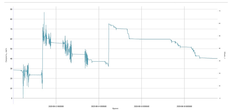
Таким образом, '''CNT''' должен увеличиваться по мере заполнения трубок датчика топливом. Оно должно изменяться от значения, близкого к калибровочному значению '''Пустой''' к калибровочному значению '''Полный'''.
Thus, CNT should increase as the sensor tubes fill with fuel. It should change from a value close to the Empty calibration value to the Full calibration value.
[[Файл:CNT_уровень_и_фактический_уровень_топлива.png|854x854пкс]]<blockquote>'''<big>ВНИМАНИЕ! РАЗБЛОКИРУЙТЕ ДРЕНАЖНЫЕ ОТВЕРСТИЯ ПОСЛЕ КАЛИБРОВКИ!!!</big>'''</blockquote>[[Файл:Разблокировка_дренажных_отверстий.png|726x726пкс]]
[[File:TankEmptyFull.png|frameless|512x512px]]<blockquote>'''<big>ATTENTION! UNBLOCK THE DRAINAGE HOLES AFTER CALIBRATION!!!</big>'''</blockquote>[[File:Unblocking drain holes.png|frameless|655x655px]]
== '''<big>Калибровка без топлива</big>''' ==
== '''<big>Calibration without fuel</big>''' ==
Альтернативным вариантом калибровки является калибровка без топлива.
An alternative calibration option is calibration without fuel.
В этом случае убедитесь, что трубки датчика пусты, в них нет топлива, но центратор должен быть вставлен в трубки. Оставьте переключатель "'''Калибровка без топлива" (1)''' активным ('''зеленый''') и нажмите "'''Откалибровать" (2)''' . Значения над кнопками Пустой и Полный изменятся автоматически.
In this case, make sure that the sensor tubes are empty and free of fuel, but the centralizer must be inserted into the tubes. Leave the '''"Calibrate without fuel"''' switch ('''1''') active ('''green''') and press '''"Calibrate"''' ('''2''') . The values above the Empty and Full buttons will change automatically.
[[Файл:Калибровка без топлива ПК.png]]
[[File:Calibration without fuel PC.png|frameless|366x366px]]
[[Файл:Калибровочные значения после калибровки без топлива ПК.png|без|мини|386x386пкс|'''<big>Калибровочные значения после калибровки без топлива</big>''' ]]
Если вы калибруете датчик без топлива, рабочий даипазон может немного измениться.
Изначально имеется два диапазона измерений:
[[File:Calibration values calibration without fuel PC.png|frameless|366x366px]]
* От 1 до 1023
If you calibrate the sensor without fuel, the operating range may change slightly.
* От 1 до 4095
Датчик никогда не отправляет значение 0. Если топлива нет, то отображается уровень 1.
Initially there are two measurement ranges:
'''При калибровке без топлива, так как датчик не знает в каком топливе будет использоваться, значение "Пустой" устанавливается на основе текущего (CNT), значение "Полный" устанавливается по формуле и, в зависимости от длинны трубок и итогового используемого топлива, диапазон может измениться.'''
* From 1 to1023
* From 1 to 4095
'''Например, при полном баке датчик будет показывать 3843 вместо 4095 или возможно, что при заполненном на 98% баке датчик уже выдаст значение 4095.'''
The sensor never sends a value of 0. If there is no fuel, level 1 is displayed.
'''Рекомендуем, по возможности, производить калибровку с топливом.'''
'''When calibrating without fuel, since the sensor does not know what fuel will be used, the "Empty" value is set based on the current (CNT), the "Full" value is set by a formula and, depending on the length of the tubes and the final fuel used, the range may change .'''
== '''<big>Установка калибровочного значение Полный и Пустой вручную</big>''' ==
'''For example, when the tank is full, the sensor will show 3843 instead of 4095, or it is possible that when the tank is 98% full, the sensor will already display the value 4095.'''
Мы не рекомендуем использовать данный функционал, но вы можете установить калибровочные значение Полный и Пустой вручную для экономии времени тогда, когда вы используете датчики одной и той же длины в одинаковые баки.<blockquote>'''<big>Внимание!!! Установка калибровочных значений вручную вероятнее всего увеличит погрешность датчика! Мы не рекомендуем делать этого!</big>'''</blockquote>Для этого, введите калибровочные значения Полный и Пустой ранее калиброванного датчика в соответствующие поля в конфигураторе.
[[Файл:Переход в инженерное меню конфигуратора ПК.png|727x727пкс]]
'''We recommend, if possible, calibration with fuel.'''
[[Файл:Переход в установку калибровочных значений вручную.png|688x688пкс]]
== '''<big>Setting the calibration value Full and Empty manually</big>''' ==
[[Файл:Установка калибровочных значение вручную ПК.png|685x685пкс]]
We do not recommend using this functionality, but you can set the Full and Empty calibration values manually to save time when you are using sensors of the same length in the same tanks.<blockquote>'''<big>Attention!!! Setting calibration values manually will most likely increase the sensor error! We do not recommend doing this!</big>'''</blockquote>To do this, enter the Full and Empty calibration values of the previously calibrated sensor into the appropriate fields in the configurator.
== '''<big>Установка режима, диапазона и сетевого адреса</big>''' ==
[[File:Wired advanced menu page.png|frameless|669x669px]]
В основном меню, вы можете изменить режим работы датчика. Название режима совпадает с интерфейсом, который используется для физического подключения датчика к GPS терминалу
Выберите режим который вам нужен('''1''') и нажмите '''“Записать параметры в устройство”'''('''2''')
== '''<big>Setting the mode, range and network address</big>''' ==
- '''Пассивный RS485''' следует выбрать, когда планируется подключать к линии А и В интерфейса RS-485 терминала. Терминал должен иметь функцию опроса датчиков, например запрашивать у них информацию. Терминал должен уметь опрашивать датчики в соответствии с '''протоколом LLS'''.
=== '''<big>Setting the mode</big>''' ===
In the main menu, you can change the operating mode of the sensor. The name of the mode coincides with the interface that is used to physically connect the sensor to the GPS tracker
- '''Частотный режим''' используется при подключении к GPS терминалу к входам, которые могут принимать и считывать сигналы в диапазоне '''300 Hz … 1323 Hz''' или '''300 Hz … 4395 Hz'''
Select the mode you need('''1''') and click '''“Save parameters to device”'''('''2''')
- '''Активный RS485 режим''' следует использовать, если терминал имеет интерфейс подключения RS-485, но не может самостоятельно опрашивать датчик, например запрашивать у него информацию; датчик будет отправлять свои показания самостоятельно каждые 2 секунды.<blockquote>'''<big>Примечание: Аналоговый выход ТД-150 всегда активен на зеленом проводе в диапзаоне 0.2-9В, не нужно отдельно его включать</big>'''</blockquote>
- '''Passive RS485''' should be selected when you plan to connect to line A and B of the tracker's RS-485 interface. The tracker must have the function of polling sensors, for example, requesting information from them. The tracker must be able to poll sensors in accordance with the '''LLS protocol'''.
Если вы настраиваете датчик на работу в режимах RS-485, Активный RS-485 или частотном режимах, вы можете выбрать диапазон '''1-1023 или 1-4095 (1)''' . В частотном режиме диапазон будет от '''300Гц до 1323 Гц или 300Гц до 4395Гц.'''
После изменения диапазона нажмите '''“Записать параметры в устройство”''' ('''2''').
- '''Frequency mode''' is used when connecting to a GPS tracker to inputs that can receive and read signals in the range '''300 Hz … 1323 Hz''' or '''300 Hz … 4395 Hz'''.
- '''Active RS485''' mode should be used if the tracker has an RS-485 connection interface, but cannot independently poll the sensor, for example, request information from it; the sensor will send its readings independently every 2 seconds.<blockquote>'''<big>Note: The analog output of the TD-150 is always active on the green wire in the 0.2-9V range, there is no need to turn it on separately</big>'''</blockquote>
'''Диапазон 1-1023''' чаще всего применяется для датчиков, которые '''короче 1 метра'''. Однако, если речь идет о стационарном танке, высота которого невелика, тогда, как длина и ширина больше 2-3 м, лучше выбрать диапазон 1-4095.
=== '''<big>Setting the range</big>''' ===
If you are configuring the sensor to operate in RS-485, Active RS-485, or Frequency modes, you can select the range '''1-1023 or 1-4095''' ('''1''') . In frequency mode, the range will be from '''300Hz to 1323Hz or 300Hz to 4395Hz'''.
After changing the range, click “'''Save the parameters to device'''” ('''2''').
Стандартно сетевой адрес датчика 1, если производится установка более одного дут или присувуют другие устройства LLS может понадобится смена сетевого адреса на датчике. Сетевой адрес каждого из датчиков, должен быть так же прописан в настройках принимающего устройства (навигационный терминал).<blockquote>'''<big>Внимание!!! на одной линии не может быть два устройства с одним сетевым адресом, это вызовет конфиликт.</big>'''</blockquote>Для смены сетевого адреса введите новый адрес в диапазоне '''0-255''' в поле "'''Изменить сет. адрес'''" ('''1''') и нажмите '''“Записать параметры в устройство”''' ('''2'''), после конфигуратор должен переключится на новый адрес датчика и отобразить новый адрес датчика в поле "'''Устройства в сети'''"('''3''') и "'''Опросить сет. адрес'''"('''4''').
[[File:Wire range settings.png|frameless|561x561px]]
[[Файл:ТД-150 после смены сетевого адреса ПК.png|без|мини|701x701пкс|'''<big>После смены сетевого адреса</big>''']]
== '''<big>Тарировка бака</big>''' ==
'''The range 1-1023''' is most often used for sensors that are '''shorter than 1 meter'''. However, if we are talking about a stationary tank, the height of which is small, but the length and width are more than 2-3 m, it is better to choose the range 1-4095.
После того, как длина датчика была подогнана под высоту бака и датчик был откалиброван, вам нужно установить его в бак.
Установить датчик в бак заведя трубки в просверленное ранее отверстие ø 30-35 мм. Убедитесь, что '''прокладка''' между датчиком и баком '''установлена'''. После этого закрутите саморезы из монтажного комплекта в просверленные ранее отверстия ø 3мм .<gallery widths="700" heights="400">
=== '''<big>Setting the network address</big>''' ===
</gallery>Приступайте к тарировке бака. В результате этой процедуры вы получите таблицу “уровень-литры” (или “уровень-галлоны”), которая позволит вашей мониторинговой платформе переводить значения уровня, которые выдает датчик в литры/галлоны, отображаемые в отчетах мониторинговой платформы.
Для того, чтобы создать такую таблицу, вам нужно заполнить бак, шаг за шагом добавляя топливо в бак порцию за порцией и записывая пары значений уровень-литры(/галлоны) после каждой порции, используя меню Тарировка в приложении.
The default network address of the sensor is 1; if more than one unit is installed or other LLS devices are added, the network address on the sensor may need to be changed. The network address of each sensor must also be specified in the settings of the receiving device (gps tracker).<blockquote>'''<big>Attention!!! There cannot be two devices with the same network address on the same line; this will cause a conflict.</big>'''</blockquote>To change the network address, enter a new address in the range '''0-255''' in the '''“Change network address”''' field ('''1''') and click '''“Save the parameters to device”''' ('''2'''), after which the configurator should switch to the new sensor address and display the new sensor address in the field '''"Available units"''' ('''3''') and '''"Poll network address"''' ('''4''').
[[File:Wired before changing Network address.png|none|thumb|611x611px|'''<big>Before changing network address</big>''']]
Предположим, вам нужно сделать тарировку бака емкостью 100 л десятью порциями по 10л.
== '''<big>Tank calibration</big>''' ==
Once the length sensor has been adjusted to the height of the tank and the sensor has been calibrated, you need to install it in the tank.
Для этого вам следует:
Install the sensor into the tank of the installed tube in the previously drilled hole ø 30-35 mm. Make sure '''the gasket is installed''' between the sensor and the tank. After this, screw the screws from the installation kit into the previously drilled ø 3mm holes.<gallery widths="700" heights="400">
File:Installing the sensor inside the tank.png|'''<big>Installing the sensor inside the tank</big>'''
File:Screwing the self-tapping screws.png|'''<big>Screwing the self-tapping screws</big>'''
</gallery>Proceed to tank calibration. This procedure will result in a "level-liters" (or "level-gallons") table that will allow your monitoring platform to convert the level values that the sensor provides into liters/gallons that are displayed in the monitoring platform reports.
* Подключить датчик
In order to create such a table, you need to fill the tank by step by step adding fuel to the tank batch by batch and recording level-liter(/gallon) pairs after each batch using the Tank calibration menu in the application.
* Проверить что фильтрация установлена на степень '''"Нет"''' ('''1'''), Фильтрация замедляет вычисление уровня и может увеличить время тарировки бака.
* Создайте Excel таблицу. Сохраните ее в формате '''.csv''' . Первая строка таблицы должна выглядеть следующим образом: [[Файл:Первая строчка тарировки в Excel.png]] Так же можно создать текстовый фаил на ПК/Телефоне или вести ручную запись тарировки
* Выбрать производится тарировка заливом или сливом. Метод '''Залив''' является рекомендуемым, так как является более точным. В случае выбора метода '''Слив''' вы не можете быть уверены в том, какое точное количество топлива находится в баке и заполнен бак или нет.
* Выбрать размер порции
<blockquote>'''ВНИМАНИЕ!''' Объем порций - это не количество порций! Это количество литров/галлонов в каждой порции! В примере ниже бак предположительно содержит 100 литров и этот объем может быть поделен на 10 порций по 10л. Если бы объем бака был 300л и его нужно было бы оттарировать в 10 порций, размер порции был бы равен 30л.</blockquote>
Suppose you need to calibrate a 100L tank in ten 10L portions.
* Начать тарировку бака заливая порции в бак или опустошая бак на заданную порцию и записывая в таблицу уровень после его стабилизации
To do this you should:
Пример тарировки заливкой порций по 10 литров и педставим, что в этом случае в баке находится 10 литров, которые нельзя удалить и при помещении датчика в бак он сразу показывает значение 115 вместо 1.
* Connect sensor
* Make sure that the filtration is set to '''“No”''' ('''1'''). Filtration slows down the level calculation and can increase the tank calibration time.
* Create an Excel table. Save it in '''.csv''' format. The first row of the table should look like this:
* [[File:First line in tank calibration table Excel.png|frameless]] You can also create a text file on your PC/Phone or manually record calibration
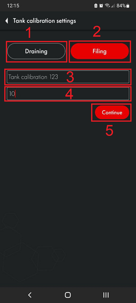
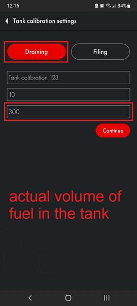
* Select whether calibration is performed by filling or draining. The '''Filling''' method is recommended as it is more accurate. If you select the '''Drain''' method, you cannot be sure what exact amount of fuel is in the tank and whether the tank is full or not.
* Select portion size
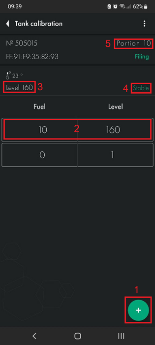
[[Файл:Тарировочная таблица, уровень 115, 10 литров.png]][[Файл:Добавление первой порции в бак.png|421x421пкс]]
<blockquote>'''ATTENTION!''' Portion volume is not the number of portions! This is the number of liters/gallons in each portion! In the example below, the tank supposedly contains 100 liters and this volume can be divided into 10 portions of 10 liters. If the volume of the tank was 300L and it needed to be divided into 10 portions, the portion size would be 30L.</blockquote>
Вы добавляете первую порцию топлива в бак. Уровень должен измениться со 115 на какой-то иное значение. Если уровень не изменяется, проверьте дренажные отверстия датчика. Они могут быть заблокированы изоляционной лентой, которую необходимо удалить после проведения калибровки датчика. Если отверстия заблокированы, воздух внутри трубок не позволит топливу попасть внутрь трубок.
* Start calibrating the tank by pouring portions into the tank or emptying the tank for a given portion and recording the level in the table after it has stabilized
[[Файл:Добавление второй порции в бак.png]]
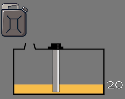
An example of calibration by filling in portions of 10 liters and imagine that in this case there are 10 liters in the tank that cannot be removed and when the sensor is placed in the tank it immediately shows the value 115 instead of 1.
Далее, добавьте следующую строку к вашей таблице.
[[File:Tank calibration first portion.png|frameless]] [[File:Adding the first portion to the tank.png|frameless|355x355px]]
[[Файл:Тарировочная таблица, уровень 223, 20 литров.png]]
You add the first portion of fuel to the tank. The level should change from 115 to some other value. If the level does not change, check the sensor drain holes. They may be blocked by electrical tape, which must be removed after the sensor has been calibrated. If the holes are blocked, the air inside the tubes will prevent fuel from getting inside the tubes.
Продолжайте так до тех пор, пока бак не заполнится.
[[File:Adding a second portion to the tank.png|frameless|447x447px]]
Однако, если имеются изгибы или другие особенности формы бака, следует уменьшить объем порций топлива до тех пор, пока уровень топлива не станет выше участка бака со сложной формой. После преодоления такого участка следует вернуться к первоначальному объему порции.
Next, add the following row to your table.
Представим, что вы делаете тарировку бака порциями в 10 литров как ранее. Уровень поднимается до участка со сложной формой.
[[File:Wired Extended table.png|frameless]]
[[Файл:Уменьшение объема порций при тарировке бака сложной формы.png|663x663пкс]]
Continue this until the tank is full.
Вы уменьшаете размер порции с 10 до 5 литров. И продолжаете добавлять порции до тех пор, пока не преодолеете участок со сложной формой.
However, if there are bends or other irregularities in the shape of the tank, the volume of fuel portions should be reduced until the fuel level is above the irregularly shaped section of the tank. After overcoming such a section, you should return to the original portion volume.
[[Файл:Возвращение к изначальному размеру порций при тарировке бака сложной формы.png|664x664пкс]]
Assume that you do the tank calibration in portions of 10 liters as before. The level rises to an area with a complex shape.
Когда уровень будет выше проблемного участка вы можете вернуться к изначальному объему порции в 10 литров.
[[File:Complex shaped tank next step.png|frameless|446x446px]]
Если в вашем случае уровень не достигает 1023 или 4095 из-за того, что бак невозможно заполнить полностью - не беспокойтесь об этом. Допустимо, что ваша таблица будет заканчиваться как на следующем примере, несмотря на то, что диапазон датчика 1-1023.
When the level is above the problem area, you can return to the original serving volume of 10 liters.
[[Файл:Таблица для бака, который нельзя заполнить на 100%.png|без|мини|'''<big>Таблица для бака, который нельзя заполнить на 100%</big>''']]
Количество порций зависит от вместимости бака. Смотрите таблицу с нашими рекомендациями ниже.
Once the tank is full, you will have a calibration chart like the following example.
[[File:Tank is full.png|frameless|499x499px]][[File:Filled tank calibration table.png|frameless|446x446px]]
[[File:Table for tank that can't be filled completely.png|none|thumb|'''<big>Table for a tank that cannot be filled 100%</big>''']]
If in your case the level does not reach 1023 or 4095 because the tank cannot be filled completely, do not worry about it. It is acceptable that your table would end up like the following example, even though the sensor range is 1-1023.
The number of servings depends on the capacity of the tank. See the table with our recommendations below.
{| class="wikitable"
{| class="wikitable"
| colspan="3" |'''<big>Рекомендуемое количество и размер порций для тарировки бака</big>'''
| colspan="3" |'''<big>Recommended number and portion size for calibrating the tank</big>'''
|-
|-
|'''<big>Емкость бака</big>'''
|'''Tank volume'''
|'''<big>Количество порций</big>'''
|'''<big>Number of portions</big>'''
|'''<big>Объем каждой порции</big>'''
|'''<big>Volume of each portion</big>'''
'''<big>(Tank Volume / Number of portions)</big>'''
'''<big>(Емкость бака / Кол-во порций)</big>'''
|-
|-
|'''<big>0-60</big>'''
|'''<big>0-60</big>'''
Line 319:
Line 375:
|'''<big>20</big>'''
|'''<big>20</big>'''
|-
|-
|'''<big>Более 1000</big>'''
|'''<big>Over1000</big>'''
| colspan="2" |'''<big>В соответствии с вашими возможностями. Главное правило: чем больше порций и меньше их объем - тем точнее будут данные</big>'''
| colspan="2" |'''<big>As per your capabilities. The rule of thumb is that the larger the portions and smaller the volume, the more accurate the data will be</big>'''
|}
|}
Основное правило: '''чем больше порций, тем выше точность отчетов на платформе'''.
<blockquote><big>The '''rule of thumb''': more portions means more accurate reports on the monitoring platform.</big></blockquote>You can create a table on your platform by loading it from a file or by entering values manually.
[[File:Loading the table on Wialon (example). .png|none|thumb|487x487px|'''<big>Loading the table on Wialon (example). Don't forget to check “Generate XY pairs” box</big>''']]
Вы можете завести таблицу на вашей платформу загрузив ее из файла или введя значения вручную.
== '''<big>Tilted tank calibration with 2 FLSs</big>''' ==
[[Файл:Загрузка таблицы на Wialon (пример). Не забудьте отметить "Генерировать пары XY".png|без|мини|687x687пкс|'''<big>Загрузка таблицы на Wialon (пример). Не забудьте отметить "Генерировать пары XY"</big>''']]
If it is not possible to level the car/tank with respect to the horizon, you can calibrate it in the tilted position of the tank.
== '''<big>Тарировка бака с 2-мя ДУТ под наклоном</big>''' ==
Technically, this kind of calibration is no different from the usual one: you pour a portion of fuel into the tank, wait for the level to stabilize, fix it, and fill in the next portion.
Если нет возможности выровнять авто\бак по отношению к горизонту, можно сделать тарировку и в положении наклона ёмкости.
Технически, такого рода тарировка ничем не отличается от обычной: Вы заливаете порцию топлива в бак, ждете стабилизации уровня, фиксируете его, заливаете следующую порцию.
However, the details of such calibration are much more important, so the algorithm of actions should be as follows:
Однако куда более важны детали такой тарировки, поэтому алгоритм действий должен быть следующий:
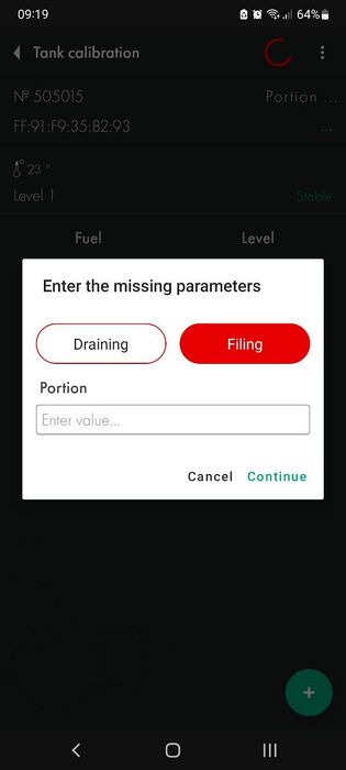
# Pour portions of fuel into the tank until the fuel level reaches the measuring tubes of the second FLS, which is located higher due to the inclination.
# When the second sensor reaches the fuel level, reduce the size of the poured portion by half. IMPORTANT: it is necessary to reduce the portion only in the calibration tables for both FLS; the actual volume of the portion being filled remains '''unchanged'''.
# Once the tubes of the sensor located lower down are completely immersed in fuel, the calibration of this FLS is considered complete.
# However, before continuing calibration of the second FLS, it is necessary to return the nominal portion volume to the original (i.e. double it). IMPORTANT: The actual portion size still remains unchanged until the tank is finally filled and the calibration process is completed.
# Заливать порции топлива в бак до тех пор, пока уровень топлива не достигнет измерительных трубок второго ДУТ, находящегося выше из-за наклона.
Thus, the resulting calculation tables (calibration tables) will be adequately accepted by the monitoring platform if a third FLS (virtual) is created in it, which is the sum of two real FLS.
# При достижении уровня топлива вторым датчиком, сократить размер заливаемой порции вдвое. ВАЖНО: сократить порцию необходимо '''только''' в тарировочных таблицах для обоих ДУТ, фактический объем заливаемой порции остается '''неизменным'''.
[[File:Tilted FLS 1.0.png|none|thumb|471x471px|'''<big>Example of FLS 1 calibration table</big>''']]
# После того, как трубки датчика, находящегося ниже по высоте, будут полностью погружены в топливо, тарировка этого ДУТ считается завершенной.
[[File:Tilted FLS 2.png|none|thumb|442x442px|'''<big>Example of FLS 2 calibration table</big>''']]
# Однако перед продолжением тарировки второго ДУТ, необходимо вернуть номинальный объем порции к исходному (т.е. повысить вдвое). ВАЖНО: фактический размер порции все еще остается неизменным до окончательного заполнения бака и завершения процесса тарировки.
Таким образом, получившиеся таблицы расчета (тарировочные таблицы) будут адекватно восприняты платформой мониторинга, если в ней будет создан третий ДУТ (виртуальный), являющийся суммой двух реальных ДУТ.
== '''<big>Calibration of a tank whose height varies along its length</big>''' ==
== '''<big>Тарировка бака, чья высота изменяется на протяжении его длины</big>''' ==
The algorithm of actions is as follows:
Такой способ тарировки во многом схож с тем, что представлен в предыдущей части.
Алгоритм действий следующий:
# Pour portions of fuel into the tank until the fuel level reaches the measuring tubes of the second FLS, which is located higher due to the difference in height.
# When the second sensor reaches the fuel level, reduce the size of the poured portion by half. IMPORTANT: it is necessary to reduce the portion only in the calibration tables for both FLS; the actual volume of the portion being filled remains '''unchanged'''.
# Continue calibrating in this manner until the tank is full.
# Заливать порции топлива в бак до тех пор, пока уровень топлива не достигнет измерительных трубок второго ДУТ, находящегося выше из-за разницы в высоте.
Thus, the resulting calculation tables (calibration tables) will be adequately accepted by the monitoring platform if a third FLS (virtual) is created in it, which is the sum of two real FLS.
# При достижении уровня топлива вторым датчиком, сократить размер заливаемой порции вдвое. '''<big>ВАЖНО</big>''': сократить порцию необходимо '''только''' в тарировочных таблицах для обоих ДУТ, фактический объем заливаемой порции остается '''неизменным'''.
[[File:Tilted FLS 1.png|none|thumb|'''<big>Example of FLS 1 calibration table</big>''']]
# Продолжать тарировку таким образом до заполнения бака
[[File:Height FLS 2.png|none|thumb|'''<big>Example of FLS 2 calibration table</big>''']]
Таким образом, получившиеся таблицы расчета (тарировочные таблицы) будут адекватно восприняты платформой мониторинга, если в ней будет создан третий ДУТ (виртуальный), являющийся суммой двух реальных ДУТ.
После того, как тарировка бака будет завершена, выберите требуемую "'''Степень фильтрации'''" и нажмите '''“Записать параметры в устройство”'''
[[Файл:Выбор степени фильтрации ТД-150 ПК.png|700x700пкс]]
Below are recommendations for choosing the filtration level for different types of vehicles:
Ниже представлены рекомендации по выбору уровня фильтрации для различных типов транспортных средств:
=== '''<big>Recommended filtration level for wired FLS</big>''' ===
=== Рекомендованный уровень фильтрации для проводных ДУТ ===
{| class="wikitable"
{| class="wikitable"
|'''<big>0-1</big>'''
|'''<big>0-1</big>'''
|'''<big>Стационарные объекты или емкости</big>'''
|'''<big>Stationary units</big>'''
|-
|-
|'''<big>2-6</big>'''
|'''<big>2-6</big>'''
|'''<big>Транспорт, передвигающийся по ровным асфальтированным дорогам</big>'''
|'''<big>Vehicles on high or medium quality roads</big>'''
|-
|-
|'''<big>7-12</big>'''
|'''<big>7-12</big>'''
|'''<big>Сельскохозяйственная техника</big>'''
|'''<big>Agricultural machinery units</big>'''
|-
|-
|'''<big>13-15</big>'''
|'''<big>13-15</big>'''
|'''<big>Тяжелая карьерная техника</big>'''
|'''<big>Heavy-duty machinery</big>'''
|}
|}
Общие советы по установке фильтрации:
General tips for installing filtration:
* Если длинна трубок меньше 30 см то уровень фильтрации должен быть установлен выше чем обычно
* If the length of the tubes is less than 30 cm, the filtration level must be set higher than usual
* Чем ближе датчик к стенкам бака тем выше фильтрация
* The closer the sensor is to the tank walls, the higher the filtration is
* Чем хуже будет покрытие дорог тем выше фильтрация
* The worse the road surface, the higher the filtration
* Нужно устанавливать только медианные тип фильтрации
* You only need to set the median filter type[[File:Filtration effect.png|none|thumb|790x790px|'''<big>Example before enabling filtering and after.</big>''']]
[[Файл:До и после включения фильтрации на датчике.png|без|мини|814x814пкс|'''<big>Пример до установки фильтрации и после.</big>''']]
== '''<big>Setting and removing a password</big>''' ==
If necessary, you can set a password on the sensor to change settings.
== '''<big>Установка и удаление пароля</big>''' ==
To do this:
При необходимости на датчик можно установить пароль на изменение настроек.
Для этого:
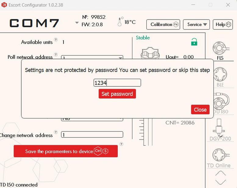
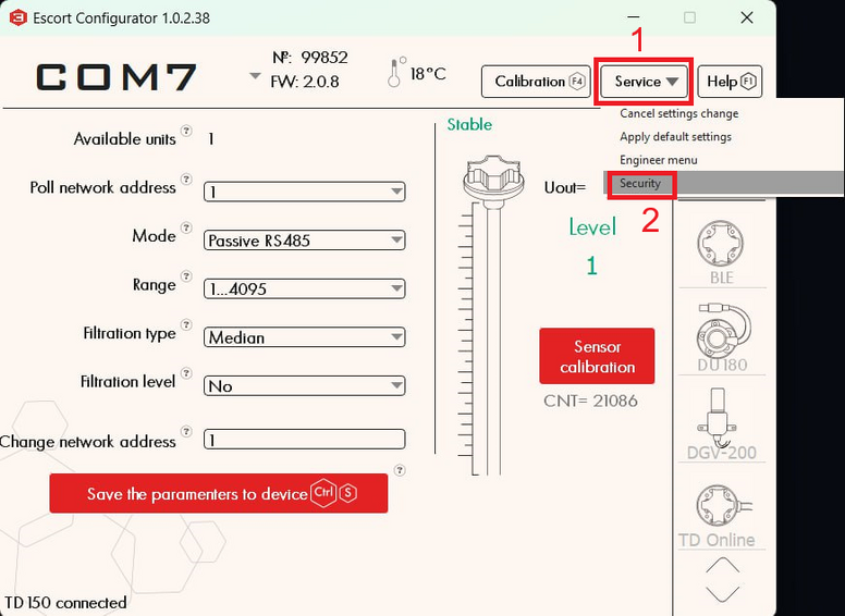
* Click on the '''"Service"''' button ('''1''') and then '''"Security"''' ('''2''')
* In the menu that opens, you can enter a password consisting of numbers and then click set password. '''Also note that the password cannot start with 0.'''
* [[File:Password menu wired.jpg|frameless|777x777px]]
* After successfully setting the password, a red lock should appear next to the FLS icon
* [[File:PC password set menu.png|frameless|781x781px]]
* Нажмите на кнопку "'''Сервис'''"('''1''') и после "'''Безопасность'''"('''2''') [[Файл:Переход в меню безопасность конфигуратор ПК.png|777x777пкс]]
<blockquote>'''<big>PLEASE NOTE THAT THE PASSWORD RESET PROCEDURE CAN BE VERY TIME-CONSUMING. WE RECOMMEND THAT YOU TAKE A RESPONSIBLE APPROACH IN SETTING YOUR PASSWORD AND SAVING IT.</big>'''</blockquote>To change the settings of a password-protected sensor or remove a password, you need to perform the password removal procedure
* В открывшемся меню вы можете ввести пароль состоящий из цифр и после нажать установить пароль '''<big>Так же обратите внимание что пароль не может начинаться с 0.</big>''' [[Файл:Установка пароля конфигуратор ПК.png|772x772пкс]]
* После удачной установки пароля ряжом с иконкой ДУТ должен появится красный замок [[Файл:Датчик запаролен конфигуратор ПК.png|771x771пкс]]
<blockquote>'''<big>ОБРАТИТЕ ВНИМАНИЕ, ЧТО ПРОЦЕДУРА СБРОСА ПАРОЛЯ ЯВЛЯЕТСЯ ВЕСЬМА ТРУДОЕМКОЙ МЫ РЕКОМЕНДУЕМ ОТВЕТСТВЕННО ОТНЕСТИСЬ К ЗАДАНИЮ ПАРОЛЯ И ЕГО СОХРАННОСТИ.</big>'''</blockquote>Для измения настроек запароленного датчика или удаления пароля вам нужно произвести процедуру удаления пароля
* Click on the '''"Service"''' button ('''1''') and then '''"Security"''' ('''2''')
* In the menu that opens, enter your password (or if you have lost your password, the master password provided by technical support) and click '''"Remove password"'''
* If the password was successfully removed, the lock should turn green
* [[File:PC wired no password menu.png|frameless|719x719px]]
* Нажмите на кнопку "'''Сервис'''"('''1''') и после "'''Безопасность'''"('''2''') [[Файл:Переход в меню безопасность конфигуратор ПК.png|777x777пкс]]
'''Attention!''' By default, there is no password set on the sensor! If you connected the sensor and a password was already set on it, contact technical support.
* В открывшемся меню введите пароль(или в случае потери пароля, мастер пароль предоставленный техподдержкой) и нажмите "'''Удалить пароль'''" [[Файл:Удаление пароля конфигуратор ПК.png|776x776пкс]]
* При удачном удалении пароля замок должен стать зеленым [[Файл:Пароль на датчике удален конфигуратор ПК.png|775x775пкс]]
'''Внимание!''' По умолчанию пароль на датчике не установлен! Если вы подключили датчик и на нем уже был задан пароль, свяжитесь с технической поддержкой.
= '''<big>Connection to the sensor, setup, calibration and calibration via a [https://play.google.com/store/apps/details?id=ru.fmeter.config mobile application on Android]</big>''' =
= '''<big>Подключение к датчику, настройка, калибровка и тарировка через [https://play.google.com/store/apps/details?id=ru.fmeter.config мобильное приложение на Android]</big>''' =
== '''<big>Connection to the sensor</big>''' ==
Wired sensors can be connected to a smartphone to the [https://play.google.com/store/apps/details?id=ru.fmeter.config Escort Configurator app]. For this you will need:
== '''<big>Подключение к датчику</big>''' ==
* Smartphone running Android operating system with OTG technology support
Проводные датчики можно подключить к смартфону к приложению [https://play.google.com/store/apps/details?id=ru.fmeter.config Эскорт конфигуратор]. Для этого вам понадобятся:
* RS-485 - USB converter, for example, Escort C200m2
* USB-OTG adapter for connecting the converter to a smartphone
* Смартфон на операционной системе Android с поддержкой технологии OTG
'''Attention! You cannot update the FW of the sensor through an application on a smartphone; this can only be done using a computer and the Bootloader program'''
* Преобразователь RS-485 - USB, например, Escort C200m2
* USB-OTG адаптер для подключения преобразователя к смартфону
'''Внимание! Через приложение на смартфоне нельзя прошить датчик, это делается только при помощи компьютера и программы Bootloader'''
By connecting the sensor to your smartphone you can:
Подключив датчик к смартфону вы сможете:
* calibrate the sensor
* change filtering level
* change network address
* select the sensor operating mode
* select measurement range (1023 or 4095)
* set or change password
* calibrate the tank
[[File:Wired phone connection.png|none|thumb|561x561px|'''<big>Diagram of sensor connection to the phone</big>''']]
[[File:Wired phone connection with add. power.png|none|thumb|565x565px|'''<big>Diagram of sensor connection to telephone with additional power supply</big>''']]
* откалибровать датчик
* Connect the sensor to your smartphone according to the diagram
* изменить уровень фильтрации
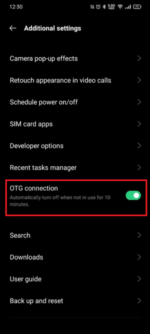
* Check that the converter is turned on (there is a power indication), on some models the OTG mode must be enabled manually in the phone settings
* изменить сетевой адрес
* [[File:OTG mode in OPPO phones.png|none|thumb|'''<big>Example of enabling OTG mode on OPPO smartphones</big>''']]
* выбрать режим работы датчика
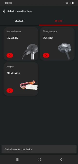
* Select the RS-485 tab ('''1''')
* выбрать диапазон измерения (1023 или 4095)
* Select Fuel level sensor ('''2''')
* задать или изменить пароль
[[File:Wired mobile app main page.png|frameless]]
* произвести тарировку бака
* When connecting for the first time, the phone should ask for access to the converter, click OK
[[File:Providing access to the C200M2.png|none|thumb|688x688px|'''<big>Providing access to the C200M2 in the app</big>''']]
* If such a request does not appear and the sensor is not detected, try connecting additional power to the sensor according to the connection diagram, also check that the power indication on the converter is active and that the OTG mode is enabled on the smartphone
* If, after asking for permission, you receive the error “Unable to connect the device,” this is normal. Just select the fuel level sensor again.
* [[File:Error mobile connection.jpg|none|thumb|685x685px|'''<big>Error failed to connect device after requesting permission</big>''']]
* If you are using a C200M inverter, you can connect an additional power supply to the inverter. To do this, you need to take a power supply for charging your smartphone with a microUSB connector and connect it to the C200M using the ADD PWR connector
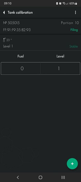
* Once connected successfully, you will see the main screen of the sensor.
[[File:Wired mobile data page.png|frameless|787x787px]]
[[Файл:Схема подключения датчика к телефону.png|без|мини|518x518пкс|'''<big>Схема подключения датчика к телефону</big>''']]
# Sensor serial number
[[Файл:Схема подключения датчика к телефону с подачей дополнительного питания.png|без|мини|523x523пкс|'''<big>Схема подключения датчика к телефону с подачей дополнительного питания</big>''']]
# Sensor firmware version (FW)
# Sensor temperature
# Network address of the polled sensor (This address is used when connecting in RS485 mode)
# Current sensor operating mode
# Current filtration type and level
# Current sensor level
# Connected sensor model
* Подключите датчик к смартфону согласно схеме
== '''<big>Sensor calibration (via mobile app)</big>''' ==
* Проверьте что преобразователь включился (имеется индикация питания), на некоторых моделях режим OTG необходимо включить вручную в настройках телефона[[Файл:Режим OTG на телефонах OPPO.png|без|мини|'''<big>Пример включения режима OTG на смартфонах OPPO</big>''']]
After you have lengthened or shortened the sensor tubes, you need to carry out the sensor calibration procedure.
* Выберете вкладку RS-485 ('''1''')
* Выберете Датчик уровня топлива ('''2''')
[[Файл:Подключение к дут через мобильное приложение.png|659x659пкс]]
* При первом подключении телефон должен попросить доступ к преобразователю, нажмите ОК
[[Файл:Предоставление доступа приложению к С200М2.png|без|мини|'''<big>Предоставление доступа приложению к С200М2</big>''']]
* Если такой запрос не появляется и датчик не обнаруживается - попробуйте подключить дополнительное питание к датчику согласно схеме подключения, так же проверьте что индикация питания на преобразователе активна и что режим OTG включен на смартфоне
* Если после запроса разрешения выходит ошибка "Не удалось подключить устройство, это нормально. Просто еще раз выберите датчик уровня топлива.[[Файл:Ошибка не удалось подключить устройство после запроса разрешения.png|без|мини|'''<big>Ошибка не удалось подключить устройство после запроса разрешения</big>''']]
* Если вы используете преобразователь C200M, то вы можете подключить дополнительный источник питания к преобразователю. Для этого вам нужно взять блок питания для зарядки смартфона с разъемом microUSB и подключить его к C200M к разъему ADD PWR
* После успешного подключения вы увидите главный экран датчика.
[[Файл:Параметры ТД-150 при подключении через мобильное приложение.png]]
# Серийный номер датчика
To do this you need:
# Версия прошивки датчика (FW)
# Температура датчика
# Сетевой адрес опрашиваемого датчика (Этот адрес используется при подключении в режиме RS485)
# Текущий режим работы датчика
# Текущий тип и степень фильтрации
# Текущий уровень датчика
# Модель подключенного датчика
== '''<big>Калибровка датчика</big>''' ==
* Go to the '''"Settings"''' menu
После того, как вы удлинили или укоротили трубки датчика - необходимо провести процедуру калибровки датчика.
Для этого необходимо:
[[File:Wired mobile settings button.png|frameless|928x928px]]
* Перейти в меню "'''Настройки'''"
* Insert the centralizer into the tubes
* Fill the tubes with fuel (by sealing the drain holes with duct tape and filling the tubes, turning the sensor upside down, or submerging the sensor tubes completely in fuel)
* Wait for the CNT level to stabilize ('''2''')
* Deselect the '''"Calibration without fuel"''' slider ('''1''')
* Press '''"Full"''' ('''3''')
* The value '''"Full"''' ('''4''') should change to a value close to the value of the current CNT ('''2'''), but not equal to it, since this value is set according to the temperature compensation of the sensor
[[Файл:Переход в настройки ТД-150 в мобильном приложении.png|1000x1000пкс]]
[[File:Wired mobile settings page.png|frameless|408x408px]]
[[File:Centralizer.png|none|thumb|512x512px|'''<big>Centrator on the tubes</big>''']]
<gallery widths="350" heights="300">
File:Closing the drain holes, rotating the sensor, and filling the tubes with fuel.png|'''<big>Closing the drain holes, inverting the sensor and filling the tubes with fuel</big>'''
File:Filling the tubes by immersing the sensor in fuel (drain holes open).png|'''<big>Filling the tubes by immersing the sensor in fuel (drain holes open)</big>'''
</gallery>
* Вставьте центратор в трубки
* Empty the tubes of fuel, leave the centralizer in the tubes
* Наполните трубки топливом (заклеив дренажные отверстия изолентой и наполнив трубки перевернув датчик или погрузив трубки датчика полностью в топливо)
* Wait for CNT to stabilize ('''2''')
* Дождитесь стабилизации уровня CNT ('''2''')
* Click '''"Empty"''' ('''3''')
* Уберите выделение с ползунка "'''Калибровка без топлива'''" ('''1''')
* The value '''"Empty"''' ('''4''') should change to a value close to the value of the current CNT ('''2'''), but not equal to it, since this value is set according to the temperature compensation of the sensor
* Нажмите "'''Полный'''" ('''3''')
* Значение "'''Полный'''"('''4''') должно измениться на значение близкое к значению текущего CNT ('''2'''), но не равно ему, так как данное значение задается согласно термокомпенсации датчика
[[Файл:Установка полного ТД-150 в мобильном приложении.png|990x990пкс]]
[[Файл:Центратор_на_трубках.png|без|мини|670x670пкс|'''<big>Центратор на трубках</big>''']]
<gallery widths="350" heights="300">
Файл:Закрытие дренажных отверстий, переворачивание датчика и заполнение трубок топливом.png|'''<big>Закрытие дренажных отверстий, переворачивание датчика и заполнение трубок топливом</big>'''
Файл:Заполнение трубок погружением датчика в топливо (дренажные отверстия открыты).png|'''<big>Заполнение трубок погружением датчика в топливо (дренажные отверстия открыты)</big>'''
</gallery>
* Опустошите трубки от топлива, оставьте центратор в трубках
Thus, '''CNT''' should increase as the sensor tubes fill with fuel. It should change from a value close to the '''Empty''' calibration value to the '''Full''' calibration value.
* Дождитесь стабилизации CNT ('''2''')
* Нажмите "'''Пустой'''" ('''3''')
* Значение "'''Пустой'''"('''4''') должно измениться на значение близкое к значению текущего CNT ('''2'''), но не равно ему, так как данное значение задается согласно термокомпенсации датчика
[[Файл:Установка пустого ТД-150 в мобильном приложении.png|975x975пкс]]
[[File:TankEmptyFull.png|frameless|512x512px]]<blockquote>'''<big>ATTENTION! UNLOCK THE DRAINAGE HOLES AFTER CALIBRATION!!!</big>'''</blockquote>[[File:Unblocking drain holes.png|frameless|759x759px]]
Таким образом, '''CNT''' должен увеличиваться по мере заполнения трубок датчика топливом. Оно должно изменяться от значения, близкого к калибровочному значению '''Пустой''' к калибровочному значению '''Полный'''.
== '''<big>Calibration without fuel</big>''' ==
An alternative calibration option is calibration without fuel.
[[Файл:CNT_уровень_и_фактический_уровень_топлива.png|854x854пкс]]<blockquote>'''<big>ВНИМАНИЕ! РАЗБЛОКИРУЙТЕ ДРЕНАЖНЫЕ ОТВЕРСТИЯ ПОСЛЕ КАЛИБРОВКИ!!!</big>'''</blockquote>[[Файл:Разблокировка_дренажных_отверстий.png|726x726пкс]]
In this case, make sure that the sensor tubes are empty, there is no fuel in them, but the centralizer must be inserted into the tubes. Leave the '''"Calibrate without fuel"''' switch ('''1''') active ('''green''') and press '''"Calibrate"''' ('''2''') . The values above the Empty and Full buttons will change automatically.
== '''<big>Калибровка без топлива</big>''' ==
[[File:Wired calibration with fuel mobile.png|frameless|768x768px]]
Альтернативным вариантом калибровки является калибровка без топлива.
В этом случае убедитесь, что трубки датчика пусты, в них нет топлива, но центратор должен быть вставлен в трубки. Оставьте переключатель "'''Калибровка без топлива" (1)''' активным ('''зеленый''') и нажмите "'''Откалибровать" (2)''' . Значения над кнопками Пустой и Полный изменятся автоматически.
If you calibrate the sensor without fuel, the operating range may change slightly.
[[Файл:Калибровка без топлива ТД-150 в мобильном приложении.png|973x973пкс]]
Initially there are two measurement ranges:
Если вы калибруете датчик без топлива, рабочий даипазон может немного измениться.
* From 1 to 1023
* From 1 to 4095
Изначально имеется два диапазона измерений:
The sensor never sends a value of 0. If there is no fuel, level 1 is displayed.
* От 1 до 1023
'''When calibrating without fuel, since the sensor does not know what fuel will be used, the "Empty" value is set based on the current (CNT), the "Full" value is set by a formula and, depending on the length of the tubes and the final fuel used, the range may change .'''
* От 1 до 4095
Датчик никогда не отправляет значение 0. Если топлива нет, то отображается уровень 1.
'''For example, when the tank is full, the sensor will show 3843 instead of 4095, or it is possible that when the tank is 98% full, the sensor will already display the value 4095.'''
'''При калибровке без топлива, так как датчик не знает в каком топливе будет использоваться, значение "Пустой" устанавливается на основе текущего (CNT), значение "Полный" устанавливается по формуле и, в зависимости от длинны трубок и итогового используемого топлива, диапазон может измениться.'''
'''We recommend, if possible, calibration with fuel.'''
'''Например, при полном баке датчик будет показывать 3843 вместо 4095 или возможно, что при заполненном на 98% баке датчик уже выдаст значение 4095.'''
== '''<big>Setting the mode, range and network address</big>''' ==
'''Рекомендуем, по возможности, производить калибровку с топливом.'''
=== '''<big>Setting the mode</big>''' ===
In the main menu, you can change the operating mode of the sensor. The name of the mode coincides with the interface that is used to physically connect the sensor to the GPS tracker
== '''<big>Установка режима, диапазона и сетевого адреса</big>''' ==
Go to Settings
=== '''<big>Установка режима</big>''' ===
[[File:Wired mobile settings button.png|frameless|806x806px]]
В основном меню, вы можете изменить режим работы датчика. Название режима совпадает с интерфейсом, который используется для физического подключения датчика к GPS терминалу
Перейдите в настройки
Select the mode you need('''1''') and press '''“Set parameters”'''('''2''')
[[Файл:Переход в настройки ТД-150 в мобильном приложении.png|997x997пкс]]
Выберите режим который вам нужен('''1''') и нажмите '''“Записать параметры в устройство”'''('''2''')
[[File:Wired set parameters mobile.png|frameless|798x798px]]
[[Файл:Выбор режима ТД-150 мобильное приложение.png|630x630пкс]]
- '''Passive RS485''' should be selected when you plan to connect to line A and B of the tracker's RS-485 interface. The tracker must have the function of polling sensors, for example, requesting information from them. The tracker must be able to poll sensors in accordance with the '''LLS protocol'''.
[[Файл:Записать параметры в устройство ТД-150 мобильное приложение.png|1007x1007пкс]]
- '''Frequency mode''' is used when connecting to a GPS tracker to inputs that can receive and read signals in the range '''300 Hz … 1323 Hz''' or '''300 Hz … 4395 Hz'''
- '''Пассивный RS485''' следует выбрать, когда планируется подключать к линии А и В интерфейса RS-485 терминала. Терминал должен иметь функцию опроса датчиков, например запрашивать у них информацию. Терминал должен уметь опрашивать датчики в соответствии с '''протоколом LLS'''.
- '''Active RS485 mode''' should be used if the tracker has an RS-485 connection interface, but cannot independently poll the sensor, for example, request information from it; the sensor will send its readings independently every 2 seconds.<blockquote>'''<big>Note: The analog output of the TD-150 is always active on the green wire in the 0.2-9V range, there is no need to turn it on separately</big>'''</blockquote>
- '''Частотный режим''' используется при подключении к GPS терминалу к входам, которые могут принимать и считывать сигналы в диапазоне '''300 Hz … 1323 Hz''' или '''300 Hz … 4395 Hz'''
=== '''<big>Setting the range</big>''' ===
If you are configuring the sensor to operate in RS-485, Active RS-485, or Frequency modes, you can select the range '''1-1023 or 1-4095''' ('''1''') . In frequency mode, the range will be from '''300Hz to 1323Hz''' or '''300Hz to 4395Hz'''.
- '''Активный RS485 режим''' следует использовать, если терминал имеет интерфейс подключения RS-485, но не может самостоятельно опрашивать датчик, например запрашивать у него информацию; датчик будет отправлять свои показания самостоятельно каждые 2 секунды.<blockquote>'''<big>Примечание: Аналоговый выход ТД-150 всегда активен на зеленом проводе в диапзаоне 0.2-9В, не нужно отдельно его включать</big>'''</blockquote>
After changing the range, press '''“Set parameters”''' ('''2''').
=== '''<big>Установка диапазона</big>''' ===
[[File:Wired setting range mobile.png|frameless|490x490px]]
Если вы настраиваете датчик на работу в режимах RS-485, Активный RS-485 или частотном режимах, вы можете выбрать диапазон '''1-1023 или 1-4095 (1)''' . В частотном режиме диапазон будет от '''300Гц до 1323 Гц или 300Гц до 4395Гц.'''
После изменения диапазона нажмите '''“Записать параметры в устройство”''' ('''2''').
[[File:Wired set parameters mobile.png|frameless|992x992px]]
'''The range 1-1023''' is most often used for sensors that are '''shorter than 1 meter'''. However, if we are talking about a stationary tank, the height of which is small, then the length and width are more than 2-3 m, it is better to choose the range 1-4095.
[[Файл:Записать параметры в устройство ТД-150 мобильное приложение.png|979x979пкс]]
=== '''<big>Setting the network address</big>''' ===
'''Диапазон 1-1023''' чаще всего применяется для датчиков, которые '''короче 1 метра'''. Однако, если речь идет о стационарном танке, высота которого невелика, тогда, как длина и ширина больше 2-3 м, лучше выбрать диапазон 1-4095.
The default network address of the sensor is 1; if more than one unit is installed or other LLS devices are added, the network address on the sensor may need to be changed. The network address of each sensor must also be specified in the settings of the receiving device (gps tracker).<blockquote>'''<big>Attention!!! There cannot be two devices with the same network address on the same line; this will cause a conflict.</big>'''</blockquote>To change the network address, enter a new address in the range '''0-255''' in the '''“Network address”''' field ('''1''') and click “'''Set parameters'''” ('''2''')
Стандартно сетевой адрес датчика 1, если производится установка более одного дут или присувуют другие устройства LLS может понадобится смена сетевого адреса на датчике. Сетевой адрес каждого из датчиков, должен быть так же прописан в настройках принимающего устройства (навигационный терминал).<blockquote>'''<big>Внимание!!! на одной линии не может быть два устройства с одним сетевым адресом, это вызовет конфиликт.</big>'''</blockquote>Для смены сетевого адреса введите новый адрес в диапазоне '''0-255''' в поле "'''Изменить сет. адрес'''" ('''1''') и нажмите '''“Записать параметры в устройство”''' ('''2''')
[[File:Wired set parameters mobile.png|frameless|857x857px]]
Once the length sensor has been adjusted to the height of the tank and the sensor has been calibrated, you need to install it in the tank.
[[Файл:Записать параметры в устройство ТД-150 мобильное приложение.png|968x968пкс]]
Install the sensor into the tank of the installed tube in the previously drilled hole ø 30-35 mm. Make sure '''the gasket is installed''' between the sensor and the tank. After this, screw the screws from the installation kit into the previously drilled ø 3mm holes.<gallery widths="700" heights="400">
== '''<big>Тарировка бака</big>''' ==
File:Installing the sensor inside the tank.png|'''<big>Installing the sensor inside the tank</big>'''
После того, как длина датчика была подогнана под высоту бака и датчик был откалиброван, вам нужно установить его в бак.
File:Screwing the self-tapping screws.png|'''<big>Tightening screws</big>'''
</gallery>Proceed to tank calibration. This procedure will result in a "level-liters" (or "level-gallons") table that will allow your monitoring platform to convert the level values that the sensor provides into liters/gallons that are displayed in the monitoring platform reports.
Установить датчик в бак заведя трубки в просверленное ранее отверстие ø 30-35 мм. Убедитесь, что '''прокладка''' между датчиком и баком '''установлена'''. После этого закрутите саморезы из монтажного комплекта в просверленные ранее отверстия ø 3мм .<gallery widths="700" heights="400">
In order to create such a table, you need to fill the tank by step by step adding fuel to the tank batch by batch and recording level-liter(/gallon) pairs after each batch using the tank calibration menu in the application.
</gallery>Приступайте к тарировке бака. В результате этой процедуры вы получите таблицу “уровень-литры” (или “уровень-галлоны”), которая позволит вашей мониторинговой платформе переводить значения уровня, которые выдает датчик в литры/галлоны, отображаемые в отчетах мониторинговой платформы.
Для того, чтобы создать такую таблицу, вам нужно заполнить бак, шаг за шагом добавляя топливо в бак порцию за порцией и записывая пары значений уровень-литры(/галлоны) после каждой порции, используя меню Тарировка в приложении.
Suppose you need to calibrate a 100L tank in ten 10L portions.
Предположим, вам нужно сделать тарировку бака емкостью 100 л десятью порциями по 10л.
To do this, you should connect the sensor and go to settings and check that the filtering is set to 0.
Для этого вам следует подключить датчик и перейти в настройки и проверить что фильтрация установлена на 0.
Filtration slows down level calculations and can increase tank calibration time.
Фильтрация замедляет вычисление уровня и может увеличить время тарировки бака.
Then go to the tank calibration menu
После перейти в меню тарировка
[[File:Wired tank calibration mobile.png|frameless|924x924px]]
[[Файл:Переход в меню тарировки ТД-150 в мобильном приложении.png|1027x1027пкс]]
Затем, вы можете нажать '''Начать''', чтобы создать новую таблицу, или нажать '''Возобновить''', чтобы выбрать существующую таблицу из памяти смартфона и продолжить работать с ней. Если вы нажмете '''Возобновить''', вам потребуется найти файл таблицы на вашем Android устройстве, который вы создали/загрузили ранее. Выберите другую папку при помощи кнопки Главное меню ('''1''') или посредством выпадающего меню ('''2'''). Выберите таблицу и нажмите на нее ('''3''')<gallery mode="nolines" widths="300" heights="700">
Файл:Начать_или_Возобновить_тарировку.png|'''Начать или Возобновить тарировку'''
Файл:Выбор_фаила_таблицы_тарировки_для_возобновления_тарировки.png|'''Выбор фаила таблицы тарировки для возобновления тарировки'''
</gallery>Если вы нажмете Начать, потребуется также выбрать папку, в которой будет сохранена таблица('''2''') и нажмите кнопку для ее выбора ('''3''')
[[Файл:Выбор_папки_и_создание_нового_файла_тарировки.png|без|мини|750x750пкс|Выбор папки и создание нового файла тарировки]]
Затем, вы можете выбрать метод '''Залив''' или '''Слив''' ('''1, 2'''). Метод '''Залив''' является рекомендуемым, так как является более точным.
В случае выбора метода Слив вы не можете быть уверены в том, какое точное количество топлива находится в баке и заполнен бак или нет.
Then, you can click '''Start''' to create a new table, or click '''Resume''' to select an existing table from your smartphone memory and continue working with it. If you click '''Resume''', you will need to locate the table file on your Android device that you created/downloaded earlier. Select another folder using the Main Menu button ('''1''') or using the drop-down menu ('''2'''). Select the table and click on it ('''3''')<gallery mode="nolines" widths="300" heights="700">
File:Tank calibration page.jpg|'''<big>Start or Continue tank calibration</big>'''
File:Folder search numbered.png|'''<big>Selecting a tank calibration table file for resuming the tank calibration</big>'''
</gallery>If you click Start, you will also need to select the folder in which the table will be saved ('''2''') and click the button to select it ('''3''')
[[File:Start tank calibration folder wired.png|none|thumb|722x722px|'''<big>Selecting a folder and creating a new tank calibration file</big>''']]
Then, you can select the '''Fill''' or '''Drain''' method ('''1, 2'''). The '''Fill''' method is recommended as it is more accurate.
Далее, дайте файлу таблицы имя ('''3''') и установить размер порции ('''4''').<blockquote>'''ВНИМАНИЕ!''' Объем порций - это не количество порций! Это количество литров/галлонов в каждой порции! В примере ниже бак предположительно содержит 100 литров и этот объем может быть поделен на 10 порций по 10л. Если бы объем бака был 300л и его нужно было бы оттарировать в 10 порций, размер порции был бы равен 30л.</blockquote>После этого, нажмите Продолжить ('''5''').<gallery widths="400" heights="600">
If you select the Drain method, you cannot be sure what exact amount of fuel is in the tank and whether the tank is full or not.
Файл:Выбор_метода_тарировки,_названия_таблицы,_размера_порции.png|'''<big>Выбор метода тарировки, названия таблицы, размера порции</big>'''
Файл:Выбор_метода_тарировки_сливом,_выбор_объема_топлива_в_баке.png|'''<big>Выбор метода тарировки сливом, выбор объема топлива в баке</big>'''
</gallery>После этого, у вас будет таблица, в которой в первой строке будет 0 литров и уровень 1. <gallery widths="400" heights="700">
Файл:Первая строка тарировки. 0 литров-галлонов и уровень 1.png|'''<big>Первая строка тарировки. 0 литров-галлонов и уровень 1</big>'''
</gallery>Вы всегда можете приостановаить тарировку и возобновить ее.<gallery widths="400" heights="700">
Файл:Сохранение_таблицы_тарировки_и_выход_из_тарировки.png|'''<big>Сохранение таблицы тарировки и выход из тарировки</big>'''
</gallery>Таблица сохраняется автоматически после того, как вы нажимаете кнопку '''+'''.
Далее, вам следует добавить первую порцию топлива в бак. После того, как уровень изменится ('''3''') и будет отображаться как Стабильный ('''4'''), нажмите + кнопку ('''1''').
Next, give the table file a name ('''3''') and set the portion size ('''4''').<blockquote>'''ATTENTION!''' Serving volume is not the number of servings! This is the number of liters/gallons in each serving! In the example below, the tank supposedly contains 100 liters and this volume can be divided into 10 portions of 10 liters. If the volume of the tank was 300L and it needed to be packaged into 10 servings, the serving size would be 30 L.</blockquote>After this, click Continue ('''5''').<gallery widths="400" heights="600">
File:Tank calibration filling.png|'''<big>Selection of tank calibration method, table name, portion size</big>'''
File:Tank calibration draining.png|'''<big>Selection of drain tank calibration method, selection of fuel volume in the tank</big>'''
</gallery>After this, you will have a table in which the first row will be 0 liters and level 1. <gallery widths="400" heights="700">
File:Tank calibration first line.jpg|'''<big>First tank calibration line. 0 liters-gallons and level 1</big>'''
</gallery>You can always pause tank calibration and resume it.<gallery widths="400" heights="700">
File:Saving the calibration table and exiting calibration.png|'''<big>Saving the calibration table and exiting calibration</big>'''
File:Resuming tank calibration.jpg|'''<big>Resuming tank calibration</big>'''
</gallery>The table is saved automatically after you click the '''+''' button.
В этом примере уровень ('''3''') не изменяется потому, что в ходе работы над данным мануалом у нас не было топлива для проведения настоящей тарировки бака. В вашем случае, уровень должен меняться (если топливо касается трубок) и быть '''Стабильным''', прежде, чем вы нажмете кнопку '''+'''.
Next, you should add the first portion of fuel to the tank. Once the level changes ('''3''') and is displayed as Stable ('''4'''), press the '''+''' button ('''1''').
Появится следующая строка ('''2'''). Значение в колонке Топливо будет увеличиваться в соответствии с размером Шага ('''5'''), который вы указали при создании таблицы или при ее последнем изменении ('''3''') .<gallery widths="400" heights="700">
In this example, level ('''3''') does not change because during the work on this manual we did not have fuel to carry out a real calibration of the tank. In your case, the level should change (if the fuel touches the tubes) and be Stable before you press the + button.
Файл:Добавление_первой_порции_в_бак.png|'''<big>Добавление первой порции в бак</big>'''
</gallery>Вы также можете изменить любую строку нажав и удерживая ее в течении некоторого времени, после которого появится диалоговое окно. Таким образом, вы можете скорректировать возможные ошибки.
Если вы нажмете строку и удерживая ее смахнете влево - она будет удалена.
[[Файл:Удаление_строки_тарировки.gif]]
The following line ('''2''') will appear. The value in the Fuel column will increase according to the Step size ('''5''') you specified when you created the table or when you last modified it ('''3''').<gallery widths="400" heights="700">
File:Adding the first portion to the tank.png|'''<big>Adding the first portion to the tank</big>'''
File:Adding a tank calibration line.png|'''<big>Adding a tank calibration line</big>'''
</gallery>You can also change any line by pressing and holding it for some time, after which a dialog box will appear. This way you can correct possible errors.
[[File:Editing a tank calibration line.jpg|none|thumb|381x381px|<big>'''Editing a tank calibration line'''</big>]]
If you press a line and hold it and swipe left, it will be deleted.
Затем, добавьте в бак следующую порцию топлива. Дождитесь изменения и стабилизации уровня, после чего нажмите кнопку + ('''1'''). Продолжайте так, пока бак не будет заполнен.<gallery widths="400" heights="700">
Файл:Добавление_второй_порции_в_бак.png|'''Добавление второй порции в бак'''
== '''<big>Что делать, если нет возможности полностью опустошить бак?</big>''' ==
Если вы не можете полностью опустошить бак, вам следует каким-либо образом вычислить объем топлива, который находится в баке. После этого, вы можете вручную отредактировать таблицу так, чтобы она выглядела как на примере ниже. Или просто отредактируйте файл таблицы перед тем, как вы загрузите его на мониторинговую платформу.
Представим, что в баке уже находятся 10 литров топлива, которые нельзя удалить, таким образом, когда вы поместите датчик в бак, он сразу начнет показывать уровень 115, вместо 1.<gallery widths="400" heights="700">
Then, add the next portion of fuel to the tank. Wait for the level to change and stabilize, then press the '''+''' button ('''1'''). Continue this until the tank is full.<gallery widths="400" heights="700">
Файл:Добавление_первой_порции_в_бак.png|10 литров топлива в баке, которые невозможно извлечь
File:Adding a second portion to the tank.png|'''<big>Adding a second portion to the tank</big>'''
Файл:Таблица_тарировки_при_уже_имеющихся_в_баке_10_литрах.png|'''Таблица тарировки при уже имеющихся в баке 10 литрах'''
File:Adding a tank calibration line.png|'''<big>Adding a tank calibration line</big>'''
</gallery>Далее, вы можете добавить следующую порцию в бак. Значение уровня должно измениться. Если значение уровня не меняется, проверьте дренажные отверстия. Они могут быть заблокированы изоляционной лентой, которую вы, возможно, использовали во время калибровки датчика или кусками герметика.
</gallery>
Если это происходит, то воздух, запертый внутри трубок, не позволяет топливу подниматься вверх.
== '''<big>What to do if it is not possible to completely empty the tank?</big>''' ==
[[Файл:Загрузка_таблицы_на_Wialon_(пример)._Не_забудьте_отметить_"Генерировать_пары_XY".png|без|мини|687x687пкс|'''<big>Загрузка таблицы на Wialon (пример). Не забудьте отметить "Генерировать пары XY"</big>''']]
If you cannot completely empty the tank, you should somehow calculate the amount of fuel that is in the tank. After this, you can manually edit the table so that it looks like the example below. Or simply edit the table file before you upload it to the monitoring platform.
== '''<big>Тарировка бака с 2-мя ДУТ под наклоном</big>''' ==
Let's assume that there are already 10 liters of fuel in the tank that cannot be removed, so when you place the sensor in the tank, it will immediately begin to show the level of 115, instead of 1.<gallery widths="400" heights="700">
Если нет возможности выровнять авто\бак по отношению к горизонту, можно сделать тарировку и в положении наклона ёмкости.
File:Adding the first portion to the tank.png|'''<big>10 liters of fuel in the tank that cannot be removed</big>'''
File:Calibration table with 10 liters already in the tank.jpg|'''<big>Calibration table with 10 liters already in the tank</big>'''
</gallery>Next, you can add the next portion to the tank. The level value should change. If the level does not change, check the drain holes. They may be blocked by duct tape that you may have used while calibrating the sensor or by pieces of sealing compound.
Технически, такого рода тарировка ничем не отличается от обычной: Вы заливаете порцию топлива в бак, ждете стабилизации уровня, фиксируете его, заливаете следующую порцию.
If this happens, the air trapped inside the tubes prevents the fuel from rising.
[[File:Loading the table on Wialon (example). .png|none|thumb|512x512px|'''<big>Loading the table on Wialon (example). Don't forget to check “Generate XY pairs” box</big>''']]
Однако куда более важны детали такой тарировки, поэтому алгоритм действий должен быть следующий:
== '''<big>Tilted tank calibration with 2 FLSs</big>''' ==
If it is not possible to level the car/tank with respect to the horizon, you can calibrate it in the tilted position of the tank.
# Заливать порции топлива в бак до тех пор, пока уровень топлива не достигнет измерительных трубок второго ДУТ, находящегося выше из-за наклона.
Technically, this kind of calibration is no different from the usual one: you pour a portion of fuel into the tank, wait for the level to stabilize, fix it, and fill in the next portion.
# При достижении уровня топлива вторым датчиком, сократить размер заливаемой порции вдвое. ВАЖНО: сократить порцию необходимо '''только''' в тарировочных таблицах для обоих ДУТ, фактический объем заливаемой порции остается '''неизменным'''.
# После того, как трубки датчика, находящегося ниже по высоте, будут полностью погружены в топливо, тарировка этого ДУТ считается завершенной.
# Однако перед продолжением тарировки второго ДУТ, необходимо вернуть номинальный объем порции к исходному (т.е. повысить вдвое). ВАЖНО: фактический размер порции все еще остается неизменным до окончательного заполнения бака и завершения процесса тарировки.
Таким образом, получившиеся таблицы расчета (тарировочные таблицы) будут адекватно восприняты платформой мониторинга, если в ней будет создан третий ДУТ (виртуальный), являющийся суммой двух реальных ДУТ.
However, the details of such calibration are much more important, so the algorithm of actions should be as follows:
# Pour portions of fuel into the tank until the fuel level reaches the measuring tubes of the second FLS, which is located higher due to the inclination.
# When the second sensor reaches the fuel level, reduce the size of the poured portion by half. IMPORTANT: it is necessary to reduce the portion only in the calibration tables for both FLS; the actual volume of the portion being filled remains '''unchanged'''.
# Once the tubes of the sensor located lower down are completely immersed in fuel, the calibration of this FLS is considered complete.
# However, before continuing calibration of the second FLS, it is necessary to return the nominal portion volume to the original (i.e. double it). IMPORTANT: The actual portion size still remains unchanged until the tank is finally filled and the calibration process is completed.
== '''<big>Тарировка бака, чья высота изменяется на протяжении его длины</big>''' ==
Thus, the resulting calculation tables (calibration tables) will be adequately accepted by the monitoring platform if a third FLS (virtual) is created in it, which is the sum of two real FLS.
Такой способ тарировки во многом схож с тем, что представлен в предыдущей части.
[[File:Tilted FLS 1.0.png|none|thumb|466x466px|'''<big>Example of FLS 1 tank calibration table</big>''']]
[[File:Tilted FLS 2.png|none|thumb|426x426px|'''<big>Example of FLS 2 tank calibration table</big>''']]
Алгоритм действий следующий:
== '''<big>Calibration of a tank whose height varies along its length</big>''' ==
This method of calibration is in many ways similar to that presented in the previous part.
# Заливать порции топлива в бак до тех пор, пока уровень топлива не достигнет измерительных трубок второго ДУТ, находящегося выше из-за разницы в высоте.
The algorithm of actions is as follows:
# При достижении уровня топлива вторым датчиком, сократить размер заливаемой порции вдвое. '''<big>ВАЖНО</big>''': сократить порцию необходимо '''только''' в тарировочных таблицах для обоих ДУТ, фактический объем заливаемой порции остается '''неизменным'''.
# Pour portions of fuel into the tank until the fuel level reaches the measuring tubes of the second FLS, which is located higher due to the difference in height.
# Продолжать тарировку таким образом до заполнения бака
# When the second sensor reaches the fuel level, reduce the size of the poured portion by half. '''IMPORTANT''': it is necessary to reduce the portion '''only''' in the calibration tables for both FLS; the actual volume of the portion being filled remains '''unchanged'''.
# Continue calibrating in this manner until the tank is full.
Таким образом, получившиеся таблицы расчета (тарировочные таблицы) будут адекватно восприняты платформой мониторинга, если в ней будет создан третий ДУТ (виртуальный), являющийся суммой двух реальных ДУТ.
Thus, the resulting calculation tables (calibration tables) will be adequately accepted by the monitoring platform if a third FLS (virtual) is created in it, which is the sum of two real FLS.
[[File:Height FLS 2.png|none|thumb|'''<big>Example of FLS 2 calibration table</big>''']]
== '''<big>Фильтрация</big>''' ==
== '''<big>Filtration</big>''' ==
После того, как тарировка бака будет завершена, выберите требуемую "'''Степень фильтрации'''" ('''1''') и нажмите '''“Записать параметры в устройство”(2)'''
After tank calibration is completed, select the required “Filtration” ('''1''') and click “Set parameters” ('''2''')
* In the menu that opens, you can enter a password consisting of numbers and then click '''“Install”'''. '''Also note that the password cannot start with 0.'''
[[File:Wired set password mobile.jpg|frameless|728x728px]]
* Перейдите в меню "'''Доп. возможности'''"
<blockquote>'''<big>PLEASE NOTE THAT THE PASSWORD RESET PROCEDURE CAN BE VERY TIME-CONSUMING. WE RECOMMEND THAT YOU TAKE A RESPONSIBLE APPROACH IN SETTING YOUR PASSWORD AND SAVING IT.</big>'''</blockquote>
[[Файл:Переход в доп. возможности ТД-150 мобильное приложение .png]]
* В открывшемся меню вы можете ввести пароль состоящий из цифр и после нажать "'''Установить'''" '''<big>Так же обратите внимание что пароль не может начинаться с 0.</big>'''
<blockquote>'''<big>ОБРАТИТЕ ВНИМАНИЕ, ЧТО ПРОЦЕДУРА СБРОСА ПАРОЛЯ ЯВЛЯЕТСЯ ВЕСЬМА ТРУДОЕМКОЙ МЫ РЕКОМЕНДУЕМ ОТВЕТСТВЕННО ОТНЕСТИСЬ К ЗАДАНИЮ ПАРОЛЯ И ЕГО СОХРАННОСТИ.</big>'''</blockquote>
* To change the settings of a password-protected sensor or remove a password, you need to perform the password removal procedure
* Для измения настроек запароленного датчика или удаления пароля вам нужно произвести процедуру удаления пароля
* In the menu that opens, enter your password (or if you lose your password, the master password provided by technical support) and click '''“Remove”'''
'''Attention!''' By default, there is no password set on the sensor! If you connected the sensor and a password was already set on it, contact technical support..
[[Файл:Переход в доп. возможности ТД-150 мобильное приложение .png]]
* В открывшемся меню введите пароль(или в случае потери пароля, мастер пароль предоставленный техподдержкой) и нажмите "'''Удалить'''"
'''Внимание!''' По умолчанию пароль на датчике не установлен! Если вы подключили датчик и на нем уже был задан пароль, свяжитесь с технической поддержкой.
= '''<big>Connecting the sensor to the GPS tracker</big>''' =
= '''<big>Подключение датчика к GPS терминалу</big>''' =
Depending on the operating mode and purpose of the sensor, additional components are used in the power supply and signal circuits: filters, optocouplers, ballast resistors and fuses. The elements are installed in the driver’s cabin of a vehicle or other equipment. If it is not possible to install in these locations, provide them with additional protection from external climatic (for example, sun, precipitation) and operational (for example, heating, moving parts) influences. Additional components are located at a safe distance from fuel and its flammable products in explosion-proof areas.
[[Файл:Общие указания при монтаже дут.png]]
В зависимости от режима работы и назначения измерителя в цепи питания и сигнальных цепях используются дополнительные компоненты: фильтры, оптопары, балластные резисторы и предохранители. Элементы устанавливаются в кабине водителя транспортного средства или другой техники. При невозможности установки в данных местах обеспечить их дополнительную защиту от внешних климатических (например, солнце, осадки) и эксплуатационных (например, нагрев, движущиеся части) воздействий. Дополнительные компоненты размещаются на безопасном удалении от топлива и его горючих продуктов во взрывобезопасных зонах.
To protect the power circuit, use fuses of the appropriate rating (see FU1 in the diagrams).
Для защиты цепи питания использовать предохранители соответствующего номинала (см. FU1 на схемах).
'''To ensure spark protection of the power circuit, use ballast resistors of the appropriate rating (see R1 in the diagrams). Place the resistors outside the explosive zone: in the event of high-voltage surges in the sensor power line, the resistor will fail and the circuit will break, eliminating the possibility of sparking in the explosive zone.'''
'''Для обеспечения искрозащиты цепи питания использовать балластные резисторы соответствующего номинала (см. R1 на схемах). Резисторы разместить вне взрывоопасной зоны: в случае высоковольтных скачков в линии питания датчика резистор выйдет из строя и цепь разорвется, исключая возможность искрения во взрывоопасной зоне.'''
Connecting cables are laid away from parts that move and heat up during operation of the equipment. If there is no additional insulation of the connecting cable wires, use flame-retardant polymer corrugated tubes used in automotive technology.
Кабели соединительные прокладываются на удалении от движущихся и нагревающихся при работе техники частей. При отсутствии дополнительной изоляции проводов кабелей соединительных использовать не поддерживающие горение полимерные гофрированные трубки, применяемые в автотракторной технике.
== '''<big>Connection diagrams</big>''' ==
In order to connect the sensor to the GPS tracker and to the power source, use the diagram presented below.
[[File:Wired RS-485 no R.png|none|thumb|512x512px|'''<big>RS-485 connection diagram</big>''']]
[[File:Wired Frequency mode.png|none|thumb|512x512px|'''<big>Wiring diagram for Frequency output</big>''']]
[[File:Wired Analog mode.png|none|thumb|512x512px|'''<big>Analog output wiring diagram</big>''']]
<blockquote>'''<big>The TD-150 sensor has analog mode always enabled; it does not need to be enabled in the configurator!</big>'''</blockquote>
== Схемы подключения ==
== '''<big>Connection using a resistor</big>''' ==
Для того, чтобы подключить датчик к GPS терминалу и к источнику питания воспользуйтесь схемой, представленной ниже.
[[File:Wired RS-485 with R.png|none|thumb|512x512px|'''<big>RS-485 connection diagram With resistor for explosion protection certificate</big>''']]
[[Файл:Схема подключения ТД-500-ТД-150 по RS-485.png|без|мини|808x808пкс|'''<big>Схема подключения по RS-485</big>''']]
[[Файл:Схема подключения ТД-500-ТД-150 по Частотному выходу.png|без|мини|805x805пкс|'''<big>Схема подключения по Частотному выходу</big>''']]
[[Файл:Схема подключения ТД-150 по Аналоговому выходу.png|без|мини|802x802пкс|'''<big>Схема подключения по Аналоговому выходу</big>''']]
<blockquote>'''<big>У датчика ТД-150 аналоговый режим включен всегда, его не нужно включать в конфигураторе!</big>'''</blockquote>
== '''<big>Подключение с использованием резистора</big>''' ==
[[Файл:Схема подключения ТД-500-ТД-150 по RS-485 С резистором для получения сертификата взрывобезопасности .png|без|мини|807x807пкс|'''<big>Схема подключения по RS-485 С резистором для получения сертификата взрывобезопасности</big>''']]Датчики поставляются вместе с 2 резисторами. Каждый из них может быть использован вместо поставляемого предохранителя (но не вместе с ним).
'''Черный резистор''' следует использовать в том случае, если датчик запитывается '''12В''' источником питания. '''Красный резистор''' следует использовать при более высоком напряжении до '''80В''' (до '''40В''' для соблюдения сертификата соответствия).
The sensors are supplied with 2 resistors. Each can be used in place of (but not in conjunction with) the supplied fuse.
Назначения резистора заключается в разрыве линии подачи напряжения в случае ее перегрузки и предотвращении искрообразования во взрывоопасной зоне, которое могло бы возникнуть в этом случае.
'''The black resistor''' should be used if the sensor is powered by a '''12V''' power source. '''The red resistor''' should be used at higher voltages up to '''80V''' (up to '''40V''' to comply with the certificate of conformity).
[[Файл:Резисторы.png|825x825пкс]]
The purpose of the resistor is to break the voltage supply line in case of overload and to prevent sparking in the hazardous area that could occur in this case.
Для достижения взрывобезопасности датчик в любом режиме нужно подключать через резистор а не предохранитель<blockquote>'''<big>НЕ ВМЕСТЕ С ПРЕДОХРАНИТЕЛЕМ,</big>'''
[[File:Wired R with sensors.png|frameless|512x512px]]
'''<big>А ВМЕСТО ПРЕДОХРАНИТЕЛЯ</big>'''</blockquote>
= '''<big>Пломбирование датчика и кабеля</big>''' =
To achieve explosion safety, the sensor in any mode must be connected through a resistor and not a fuse.<blockquote>'''<big>NOT WITH THE FUSE, BUT INSTEAD OF THE FUSE</big>'''</blockquote>
Понадобятся защитная крышка датчика и пломба из комплекта<gallery widths="300" heights="300">
</gallery>The cover is attached to the sensor head
[[File:Wired FLS with protective cover.png|none|thumb|411x411px|'''<big>Wired FLS with protective cover</big>''']]
Then the seal itself is fixed in a special hole (it must be inserted to the end, with the '''closed end facing outwards''')
<gallery widths="400" heights="400">
<gallery widths="400" heights="400">
Файл:Установка пломбы на проводной дут.png|'''<big>Установка пломбы на проводной дут</big>'''
File:Installing a seal on a wired FLS.png|'''<big>Installing a seal on a wired FLS</big>'''
Файл:Установленная пломба на проводной дут.png|'''<big>Установленная пломба на проводной дут</big>'''
File:Installed seal on the wired FLS.png|'''<big>Installed seal on a wired FLS</big>'''
</gallery>Чтобы удалить пломбу, следует вкрутить в нее специальный ключ из комплекта (также можно использовать любой саморез подходящего размера) и потянуть его на себя.
</gallery>To remove the seal, screw the special key from the kit into it (you can also use any self-tapping screw of a suitable size) and pull it towards you.
Так же в комплекте с датчиком актуального образца имеется альтернативная пломба, если необходима номерная пломба.
* Необходимо продеть тросс через отверстие в крышке датчика [[Файл:Альтернативная пломбировка проводного дут шаг 1.png|580x580пкс]]
Thus, it will be impossible to remove the seal without damaging it. This provides additional protection against unauthorized access.
* Продеть оба конца тросса через отверстие в глове датчика [[Файл:Альтернативная пломбировка проводного дут шаг 2.png|580x580пкс]]
=== '''<big>Alternative sealing of a current design sensor</big>''' ===
Also included with the sensor of the current design is an alternative seal if a numbered seal is required.
* Продеть оба конца через пломбу, затянуть тросс и установить пломбу нажав на выпирающую часть [[Файл:Альтернативная пломбировка проводного дут шаг 3.png|750x750пкс]]
* It is necessary to pass the cable through the hole in the sensor cover
* [[File:Alternative sealing of wired FLS step 1.png|frameless|432x432px]]
== '''<big>Пломбировка датчика старого образца</big>''' ==
* Pass both ends of the cable through the hole in the sensor head
[[Файл:Пломбирование датчика в старом корпусе.png|761x761пкс]]
* [[File:Alternative sealing of wired FLS step 2.png|frameless|435x435px]]
== '''<big>Пломбировка кабеля</big>''' ==
* Pass both ends through the seal, tighten the cable and install the seal by pressing on the protruding part
Для пломбировки разъема датчика проденьте пластиковую пломбу в специальное отверстие на разъеме датчика
* [[File:Alternative sealing of wired FLS step 3.png|frameless|555x555px]]
[[Файл:Пломбирование кабеля.png]]
== '''<big>Sealing sensor of the former design</big>''' ==
[[File:Sealing sensor of the former design.png|frameless|512x512px]]
= '''<big>Обновление прошивки датчика</big>''' =
== '''<big>Cable sealing</big>''' ==
[https://docs.google.com/document/d/1N5a2UtCe8WYpmxnQ_ypkGnqHeSpMDLfLVFTuLoHpxBM/edit '''Инструкция по прошивке''']
To seal the sensor connector, insert a plastic seal into the special hole on the sensor connector
'''[https://www.youtube.com/watch?v=BvWo8sETwPY Также есть видеоинструкция]'''
[[File:Wire sealing.png|frameless|493x493px]]
'''Актуальную версию прошивки вы можете в [https://www.fmeter.ru/download/?product=TD150#escort-id22 разделе загрузок на нашем сайте]'''
= '''<big>Частые проблемы и способы их решения</big>''' =
'''[https://youtu.be/BVCs-LiWLVs There is also a video instructional guide]'''
== '''<big>Уровень 7000</big>''' ==
'''You can find the latest firmware version in the [https://www.fmeter.ru/en/download/#td150 downloads section of our website]'''
Уровень 7000 - код ошибки Короткое замыкание. Он говорит о том, что в трубках присутствует грязь, вода, стружка или иные примеси. Все это может обладать высокой проводимостью, в то время, как датчик рассчитан на работу с диэлектриками, такими как топливо.
Вас следует прочистить трубки датчика - предпочтительно продув их через дренажные отверстия сжатым воздухом.
= '''<big>Common problems and solutions</big>''' =
Если данная ошибка произошла после начала эксплуатции датчика, значит скорее всгео данные загрязнения попали в трубки датчика из бака и в данном случае так же необходимо промыть бак.
== '''<big>Level 7000</big>''' ==
Level 7000 is an error code Short circuit. This indicates that there is dirt, water, chips or other impurities in the tubes. All of these can be highly conductive, while the sensor is designed to work with dielectrics such as fuel.
== '''<big>Уровень 6500</big>''' ==
You should clean the sensor tubes preferably by flushing them with the clean fuel and blowing them through the drain holes with compressed air.
Этот код может говорить об обрыве трубок. Данный код ошибки может сгенерироваться сразу после обрезки трубок. В таком случае просто откалибруйте датчик.
Если это не помогает, проверьте CNT. Если CNT ниже 10 000, то, с большой вероятностью, можно заключить нарушен контакт трубок с платой датчика.
If this error occurred after the start of operation of the sensor, it means that most likely these impurities got into the sensor tubes from the tank and in this case it is also needed to ensure that the tank itself doesn't contain any contaminations. Clean the tank, if necessary. Note that a fuel level sensor installed outside a contaminated tank may function correctly, but the same sensor installed in such a tank may generate this error code.
Сделайте фото головы датчика (должен быть виден номер датчика), его трубок (должно быть четко видно соответствие или несоответствие длины трубок), сделайте скриншот главного экрана датчика и страницы меню '''Настройки''' в приложении и отправьте эти данные в техподдержку.
== '''<big>Level 6500</big>''' ==
This code may indicate that the tubes have lost contact. This error code may be generated immediately after cutting the tubes. In this case, simply calibrate the sensor.
== '''<big>Датчик не подключается или не определяется в приложении</big>''' ==
If this does not help, check the CNT. If the CNT is below 10,000, it is very likely that the tubes are not in contact with the sensor board.
Если датчик не подключается к конфигуратору, проделайте следующее:
* Убедитесь в том, что выбран верный номер СОМ порта и в том, что установлены драйвера и библиотеки (STMicroelectronics Virtual COM Port ('''1''')(С200М) или USB-SERIAL CH341A ('''2''')(C200М2) в пункте COM и LPT порты диспетчера устройства Windows "для входа в данное меню нажмите '''win+r''' и введите '''devmgmt.msc''' и нажмите '''ОК'''('''3''') и после раскройте подменю ком портов ('''4''')" [[Файл:Ком порты С200М и С200М2.png|877x877пкс]] [[Файл:Выбор ком порта и ДУТ.png]]
Take a photo of the sensor head (the sensor serial number should be visible), its tubes (the correspondence or discrepancy of the tubes length should be clearly visible), take a screenshot of the main screen of the sensor and the Settings menu page in the application and send these data to tech support.
* Если возможно, подключите другой датчик, который точно работает; если он подключается, тогда проблем с СОМ портом или преобразователем нет
* Подключите другой USB кабель к С200М (разъем ADD PWR); проверьте исправен ли USB кабель
== '''<big>The sensor does not connect or is not recognized in the application</big>''' ==
* Если используется иной преобразователь, убедитесь, что на датчик подается достаточное питание (12 вольт оптимально)
If the sensor does not connect to the configurator, do the following:
* Подключая датчик, нажмите Search for sensors в течении 15 секунд после подачи питания на датчик
* Если вышеперечисленное не помогло - перепрошейте датчик
* Если не удается завершить прошивку, обратитесь в нашу техподдержку
== '''<big>Проверка подключения между датчиком и терминалом по RS-485</big>''' ==
* Make sure that the correct COM port number is selected and that drivers and libraries are installed (STMicroelectronics Virtual COM Port ('''1''')(C200M) or USB-SERIAL CH341A ('''2''')(C200M2) in the COM and LPT ports section of the Windows device manager "to enter this menu, press '''win+r''' and enter '''devmgmt.msc''' and press '''OK''' ('''3''') and then expand the com ports submenu ('''4''')"
Если датчик, по какой-либо причине, после того, как вы все верно настроили, не передает данные на терминал, необходимо выяснить, происходит ли обмен данными между устройствами.
* If possible, connect another sensor that is sure to work; if it connects, then there are no problems with the COM port or converter
Для этого, подключите датчик к терминалу по RS-485. Подайте питание на оба устройства.
* Connect another USB cable to the C200M (ADD PWR connector); check if the USB cable is working
* If another converter is used, ensure that sufficient power is supplied to the sensor (12 volts is optimal)
* When connecting the sensor, press Search for sensors within 15 seconds after power is applied to the sensor
* If the above does not help, reflash the FW of the sensor
* If you cannot complete the firmware, contact our technical support
После этого возьмите преобразователь RS-485-USB и подсоедините его между датчиком и терминалом так, как показано ниже:
== '''<big>Checking the connection between the sensor and the tracker via RS-485</big>''' ==
If the sensor, for some reason, after you have configured everything correctly, does not transmit data to the tracker, you need to find out whether data is being exchanged between devices.
Для RS-485 линии А и В конвертера должны быть подключены к линиям А и В датчика
To do this, connect the sensor to the tracker via RS-485. Connect power to both devices.
[[Файл:Подключения для снятие лога RS-485 .png|без|мини|820x820пкс|'''<big>Подключения для снятие лога RS-485</big>''' ]]
Запустите [https://drive.google.com/file/d/10i7v4TZ9-JDJYPAh-9JSh4x6vkM93BVV/view?usp=sharing terminal.exe] и настройте СОМ порт как показано ниже:
After that, take the RS-485-USB converter and connect it between the sensor and the tracker as shown below:
For RS-485, lines A and B of the converter must be connected to lines A and B of the sensor
Также, отметьте HEX или ASCII в зависимости от того, в каком формате будут передаваться информация от датчика. Для всех датчиков, кроме TD-600 настроенного в режиме RS-232, нужно выбрать HEX.
Also, check HEX or ASCII depending on the format in which information from the sensor will be transmitted. For all sensors except the TD-600 configured in RS-232 mode, you must select HEX.
После правильного подключения преобразователя выберите СОМ порт и нажмите Connect. Если датчик опрашивается терминалом и отвечает, то все в порядке.
After connecting the converter correctly, select the COM port and click Connect. If the sensor is polled by the tracker and responds, then everything is in order.
[[Файл:Датчик отвечает терминалу по RS-485.png|без|мини|667x667пкс|'''<big>Датчик отвечает терминалу по RS-485</big>''']]
[[File:Sensor responds to the terminal via RS-485.png|none|thumb|572x572px|'''<big>Sensor responds to the terminal via RS-485</big>''']]
Если нет обмена данными между двумя устройствами, попробуйте опросить датчик вручную.
If there is no communication between the two devices, try polling the sensor manually.
Для этого, введите запрос '''31$01$06$6C''' для датчика с сетевым адресом 1 и нажмите '''Send'''
To do this, enter the request '''31$01$06$6C''' for the sensor with network address 1 and click '''Send'''
[[Файл:Отправка запроса на датчик.png|без|мини|673x673пкс|'''<big>Отправка запроса на датчик</big>''']]
[[File:Sending a request to the sensor.png|none|thumb|585x585px|'''<big>Sending a request to the sensor</big>''']]
Структура запроса зависит от сетевого адреса датчика. Если вы измените адрес датчика на 255, например, то запрос будет выглядеть следующим образом
The structure of the request depends on the network address of the sensor. If you change the sensor address to 255, for example, then the request would look like this
'''31$FF$06$29'''
'''31$FF$06$29'''
'''FF''' - 255 в HEX
'''FF''' - 255 in HEX
'''29''' - контрольная сумма '''CRC''' рассчитанная для конкретного запроса
Для того, чтобы посчитать контрольную сумму, вы можете перейти на сайт '''[https://crccalc.com/ crccalc]''' и ввести ваш запрос без знака '''$''', выбрать HEX, CRC-8/MAXIM и нажать Calc CRC-8
'''29''' - '''CRC''' checksum calculated for a specific request
[[Файл:Расчет CRC для адреса 255.png|без|мини|678x678пкс|'''<big>Расчет CRC для адреса 255</big>''']]
Если датчик опрашивается терминалом и отвечает, то все в порядке.
Если датчик не отвечает терминалу, но отвечает на запрос, который вы отправляете вручную, вам следует проверить порты RS-485 вашего терминала.
In order to calculate the checksum, you can go to the '''[https://crccalc.com/ crccalc]''' website and enter your request without the '''$''' sign, select HEX, CRC-8/MAXIM and click Calc CRC-8
[[File:CRC calculation for address 255.png|none|thumb|665x665px|'''<big>CRC calculation for address 255</big>''']]
If the sensor is polled by the tracker and responds, then everything is in order.
Если датчик не отвечает ни на что - следует провести стандартную процедуру диагностики ДУТ
If the sensor does not respond to the tracker, but responds to a request you send manually, you should check your tracker's RS-485 ports.
= '''<big>Описание протокола LLS</big>''' =
If the sensor does not respond to anything, the standard FLS diagnostic procedure should be carried out.
Протокол описан в данном [https://docs.google.com/spreadsheets/d/12cmqjmKU7KKg6ms8wnTsv6Ttb1gohf8b/edit?usp=sharing&ouid=113197106569288024895&rtpof=true&sd=true документе]
Пример запроса и ответа для 1 сетевого адреса:
= '''<big>Description of the LLS protocol</big>''' =
The protocol is described in this [https://docs.google.com/spreadsheets/d/1maRSrToEaYtOP0sQz69Qq3e0iA0dBRos/edit?usp=drive_link&ouid=113197106569288024895&rtpof=true&sd=true document]
Запрос: '''''31 01 06 6С'''''
Example of a request and response for 1 network address:
Ответ от датчика: '''''3E 01 06 19 01 00 92 5D BE'''''
Request: '''''31 01 06 6C'''''
= '''<big>Назначение контактов и проводов</big>''' =
= '''<big>Удаленное управление ДУТ Эскорт</big>''' =
= '''<big>Purpose of contacts and wires</big>''' =
На данный момент у терминалов Навтелеком и ГлонассСофт имеется возможность настройки проводных ДУТ Эскорт путем удаленного подключения к нав.терминалу без использования вышеупомянутых команд. Сделать это можно согласно данным инструкциям:
[[File:Pinout TD-150.png|frameless|828x828px]]
'''[https://youtu.be/n_HxgImFvPs Смарт и Сигнал, встроенный конфигуратор]'''
= '''<big>Remote control of FLS Escort</big>''' =
At the moment, Navtelecom and GlonassSoft trackers have the ability to configure wired Escort FLS by remotely connecting to the gps tracker without using the above commands. This can be done according to these instructions:
'''[https://youtu.be/npxXyVOtfh0 Смарт и Сигнал через создание команд в конфигураторе]'''
'''[https://www.youtube.com/watch?v=qmU9DQCO4Fc Smart and Signal, built-in configurator]'''
'''[https://youtu.be/JJZl-EsrUoQ Smart and Signal by creating commands in the configurator]'''
'''[https://youtu.be/rFzWX8E97Bg UMKa]'''
Так же возможна отправка команд через смс команды или терминал трекера.
It is also possible to send commands via SMS commands or tracker tracker.
На данный момент, нам известно что функцию удалённого управления поддерживают трекеры семейства Смарт и Сигнал производства Навтелеком (Сигнал, Смарт), Техноком (АвтоГРАФ) и ГлонассСофт (УМКа). Передача команд на датчик возможна только в режиме работы RS-485.
At the moment, we know that the remote control function is supported by trackers of the Smart and Signal family produced by Navtelecom (Signal, Smart), Technocom (AvtoGRAPH) and GlonassSoft (UMKa). Transmission of commands to the sensor is possible only in RS-485 operating mode.
Для начала Вам необходимо открыть [https://www.fmeter.ru/download/_ftp/all/dut/FLS_Configurator.zip?v=210521143455 ПК-конфигуратор Эскорт]; преобразователь и\или трекер, при этом, должны быть отсоединены от компьютера. Во вкладке '''''Сервис''''' кликните на опцию '''''Дистанционное управление'''''.
First you need to open the [https://www.fmeter.ru/download/_ftp/all/dut/FLS_Configurator.zip?v=210521143455 PC configurator Escort]; The converter and/or tracker must be disconnected from the computer. In the '''Service''' tab, click on the '''Remote control''' option.
[[Файл:Переход во вкладку Дистанционное управление.png|750x750пкс]]
[[File:Remote control Settings.png|frameless|632x632px]]
Откроется окно формирования команд для отправки:
A window for generating commands for sending will open:
[[File:Remote control Settings menu.jpg|frameless|586x586px]]
Здесь необходимо:
Here you need:
# Выбрать, какого рода команду необходимо сформировать
# Choose what type of commandd to generate
# Указать текущий сетевой адрес датчика, на который будет отправлена команда
# Specify the current network address of the sensor to which the command will be sent
# Указать параметры, которые необходимо изменить данной командой
# Specify the parameters that need to be changed by this command
# Нажать на кнопку '''''Сгенерировать'''''
# Click on the '''Generate''' button
# Затем нужно отправить выделенную часть команды через конфигуратор трекера или СМС-сообщением на номер действующей SIM-карты данного GPS-терминала
# Then you need to send the selected part of the command via the tracker configurator or by SMS message to the number of the current SIM card of this GPS tracker
ВНИМАНИЕ: если на датчике установлен пароль, то нужно сначала отправить команду на ввод пароля, а затем команду, которая Вам нужна.
ATTENTION: if a password is set on the sensor, you must first send a command to enter the password, and then the command that you need.
[[Файл:Процесс формирования команды.png|755x755пкс]]
Для расшифровки ответа на отправленную команду необходимо:
To decrypt the response to the sent command, you need:
# Скопировать ту часть ответа от трекера, которая начинается с '''''3Е01…''''', и вставить его в поле ввода\вывода во вкладке ''Дистанционное управление'' конфигуратора Эскорт
# Copy that part of the response from the tracker that begins with '''3E01...''', and paste it into the input/output field in the ''Remote control'' tab of the Escort configurator
* '''<big>[https://www.fmeter.ru/download/_ftp/datchik-urovnja-topliva/eskort-td-150/%D0%9F%D0%B0%D1%81%D0%BF%D0%BE%D1%80%D1%82_%D0%A2%D0%94-150.pdf?v=271022141709 Technical data sheet of the device]</big>'''
High-precision fuel level sensors (FLS, also meters or sensors) of the Escort brand are designed to determine the filling level of petroleum products in fuel tanks, reservoirs and storage tanks. The TD-150 meter (sensor) is used in transport technology as a fuel level meter, in industry - as a level meter for any light petroleum products. Escort FLS measurement type is capacitive. Its readings are based on the dielectric constant of the medium in which it operates; in this case, the medium is various types of light petroleum products (gasoline, diesel, kerosene, motor oil).
Fuel level sensor (FLS) - device which is used for measuring fuel level.
Serial number - code consisting of letters and numbers assigned to a device (sensor).
CNT - an oscillatory circuit, thanks to which the basic level of filling of the sensor measuring tubes with fuel is calculated. This level is converted to a final value determined by the data interface.
Data transfer protocol - a set of specific logical-level rules or conventions that govern the exchange of data between different programs or devices. For TD-150, the main transmission protocol is LLS via the RS-485 interface.
Data transfer mode - this is a type of boundary between two objects or nodes, which are regulated by a special accepted standard and implemented using established methods, tools and rules. TD-150 has the following operating modes:
RS-485 (Passive and Active)
Analog
Frequency
Interface - a physical connection method and/or a set of software tools that allows data to be transferred between two or more devices.
RS-485 - digital data transmission mode. The sensor waits for a corresponding request from the receiving device. Works using the LLS protocol. Based on CNT, a value is generated in conventional units of the selected range (1-1023 units or 1-4095 units)
Converter - digital converter RS-485 to USB (С200М или С200М2) for configuring wired sensors.
Active (periodic) RS-485 - operating mode in which the sensor, without waiting for a request from the receiver, itself transmits packets with command data within 2 seconds.
Analog - mode in which a corresponding voltage is generated based on the CNT in the approximate range of 0.2-9V.
Frequency - mode in which the corresponding frequency in Hz is generated based on the CNT (301-1323 Hz with a value range of 1-1023; 301-4395 Hz with a value range of 1-4095).
GPS tracker - the main element of the system for monitoring the operation of transportation carried out by means of satellite communication. Without it, it is impossible to control transportation, to determine the coordinates of the vehicle location. It collects information from sensors and on-board system of the vehicle, and then transmits it to the device/server, which belong to the controlling specialist.
Preparation
Preparing the Tank
To prepare the tank you should:
Empty the tank, clean and dry if necessary
Remove fuel vapors and air from the tank (especially for a gasoline tank, but in the case of a diesel engine, this procedure should not be neglected, since gasoline could be added to the diesel); to do this, you can heat water to boiling point and direct the resulting steam into the tank or use carbon dioxide so that it displaces fuel vapors and air; ensure that any open flame sources are sufficiently far away from the fuel tank
Find the geometric center of the tank and drill a hole in it using a ø3mm drill bit. Then, using a piece of stiff wire, examine the tank for the presence of partitions in it
Choosing a location for installing the FLSDrilling the tank and subsequent examination of the tank for the presence of partitionsDrilling a hole at an angleRemoving a Drilled DiscIf the space inside the tank in the selected location is free, drill a ø 35 mm hole using a bimetallic bit; When drilling, keep the bit tilted slightly to prevent the cut section from falling into the tank. Use a magnet to catch chips and prevent them from getting into the tank.
If it is impossible to install the sensor in the geometric center of the tank, try choosing another location as close as possible to the geometric center of the tank; this point should coincide with the place where the height of the tank is maximum. This way you reduce the risk and amplitude of level fluctuations associated with fuel movement while driving.
Why should the sensor be mounted in the geometric center of the tank?
The highest point must be chosen so that the sensor can measure the level of all the fuel inside the tank without any blind spots.
The fuel level readings from a sensor installed in the center of the tank will be least affected by movement and fuel overflow in the tank.
If it is not possible to install the sensor in the center of the tank, consider installing two sensors diagonally at two corners. When fuel flows to one side of the tank, the level on the corresponding sensor will rise, and on the opposite side, the level will correspondingly decrease, while the average level will remain unchanged.
Attention: Before starting the calibration, the vehicle/fuel tank must be positioned flat in relation to the horizon, i.e. on a level surface without a slope.
If the tank has an irregular geometric shape, the sensor must be installed at the maximum depth of the tank, closer to the geometric center.
The sensor is installed in the highest place of the tank
When installation in the center is impossible - two or more FLS.
To increase accuracy and reduce level fluctuations, install two sensors in one tank. This solution is mainly used in tanks with a capacity of more than 600 liters and having a length of 1500 mm. Sensors must not be installed close to the walls of the tank.
Also, two or more sensors should be installed if it is not possible to install the sensor in the center of the tank and (or) the tank has an elongated shape, i.e. The length of the tank is significantly greater than its height.
Two sensors installed diagonally
Note. Installing a single sensor in an elongated tank will allow you to detect drains and refills. But increased level fluctuations while driving may not allow the monitoring platform to correctly read fuel consumption. Therefore, installing two sensors is preferable.
Installation locations in tanks of complex shapes
Saddle-Style Fuel Tanks
In this case, it is desirable to install two fuel level sensors in the deepest places along the geometric center of the depressions.
Cylindrical tank
In this case, the sensor must be installed in the geometric center of the tank.
Long cylindrical tank
In the case of elongated cylindrical tanks, to improve readings while driving, it is necessary to install two sensors at an equal distance from the geometric center of the tank.
Ladder shape tank
If there is a difference in height in the tank and there is no common bed, it may be necessary to install two fuel level sensors.
Ladder shape tank's tank calibration
When calibrating, it is necessary to create two tables, one for "FLS 1" and the second for "FLS 2"
Let's assume that the calibration step is 10 liters.
At the beginning of calibration, when the fuel is in the "Red Zone", the level changes will only occur on "FLS 2", so we directly add calibration steps of 10 liters to the table for "FLS 2".
When the fuel is in the "Yellow Zone" changes will occur on both "FLS 1" and "FLS 2", during this period we record changes in both tables with half a step, that is, we also fill in 10 liters, but we record 5 liters in the table of each sensor.
When the fuel is in the "Green Zone" the changes will only occur on "FLS 1" so we directly add calibration steps of 10 liters to the table for "FLS 1".
On the platform "FLS 1" and "FLS 2" are started as separate sensors with their own tables and then a third virtual sensor is created with the sum of liters for two sensors, an example of starting two FLS on the platform is shown in this instruction.
Preparing the sensor
Preparing the sensor tubes
Before calibrating the sensor, you should determine the future length of the measuring tubes in accordance with the height of the tank and cut or extend them. The length of the tubes should be calculated according to the following formula:
L = H - 15 mm,
where L - tubes length after changing the length
and
H - height of the tank at the installation point.
ATTENTION!!!The minimum length of the tubes should not be less than 15 cm (150 mm). Otherwise, it will most likely not be possible to obtain adequate graphics. The maximum length of the tubes can reach 6m.
Measuring height of the tankMeasuring the length of tubes
Use a hacksaw to cut the tubes. When sawing, be careful not to damage the connection of the tubes to the circuit board inside the sensor head and to prevent metal shavings from falling into the tubes.
Cutting the tubes
Avoid getting shavings inside the tubes - this may lead to a short circuit in the sensor; if this happens, blow the tubes with compressed air through the drainage holes under the sensor flange. Sand the edges of the tubes with sandpaper to remove any burrs or irregularities.
To extend sensor tubing, use a collet extension and an additional tube.
Collet connection
Inner nuts (yellow elements) are used to connect the inner tubes. Once they are installed and the studs are screwed into them, the tubes do not have to touch each other, but try to get them as close to each other as possible.
Internal connection of the collet connection
The outer coupling and the corresponding nuts must be securely tightened. The outer tubes should touch each other.
Installation of the configurator and connection to the sensor
The sensor can be configured using the configurator on a PC (From here onwards- "configurator").
Connect the sensor to the USB-RS-485 converter using a 6-pin MOLEX connector or using cable clamps if a cable route is connected to the sensor. Orange wire is line A of the RS-485 sensor interface, white wire is line B of the RS-485 sensor interface, black wire is GND, red is PWR.
Sensor connected via MOLEXSensor connected via cables and cable clamps
We recommend using our Escort C200M/C200M2 USB-RS-485 converter, since we cannot guarantee 100% compatibility of our devices with converters from other brands.
When working with a laptop, we recommend connecting it to the power supply and/or connecting an additional USB cable to the ADD connector of the PWR C200M. Otherwise, there may not be enough power to operate the sensor and transmitter.
Along with installing the configurator 1.0.2.38, the drivers for the C200M will be installed automatically.
If you use C200M2 on Windows 10 and 11 operating systems, drivers should be installed automatically from Windows Update, on the Windows 7 operating system and below, you may need to disable the electronic signature of drivers and manually install drivers for the С200M2.
If the driver was installed correctly, then after connecting the converter to your PC/laptop, you will see the STMicroelectronics Virtual COM Port (1)(C200M) or USB-SERIAL CH341A (2)(C200M2) device in the COM and LPT ports section of the Windows device manager " to enter this menu, press win+r and enter devmgmt.msc and press OK (3) and then expand the com ports submenu (4)"
The com port number displayed in this menu is also needed to connect the sensor.
After connecting the converter, sensor to it and checking the installation of drivers by checking the com port number of the converter, you need to open the configurator, select the desired com port which we could find in the device manager (1) and press the FLS button (2).
The connection to the FLS should be made within 15 seconds after the sensor has been connected to power, if the sensor operating mode has been changed from RS-485 to any other.
After connecting the sensor you should see this menu:
Sensor serial number
Sensor firmware version (FW)
Sensor temperature
Current sensor level
Current CNT level (raw level value) of the sensor
LLS network addresses connected to this converter (if there is more than one address in this list, it means either more than one sensor is connected to the line at the same time or there is interference on the line, in this case it is necessary to check the connection to the FLS for the presence of other conflicting devices and it is necessary to close other programs using the com ports for example tracker configurator)
Network address of the polled sensor (This address is used when connecting in RS485 mode)
Current sensor operating mode
Current range of output values (1-1023 or 1-4095)
Current filtration type and degree
Connected sensor model
Sensor calibration
After you have lengthened or shortened the sensor tubes, you need to carry out the sensor calibration procedure.
To do this you need:
Go to menu "Sensor calibration"
Insert the centralizer into the tubes
Fill the tubes with fuel (by sealing the drain holes with duct tape and filling the tubes, turning the sensor upside down, or submerging the sensor tubes completely in fuel)
Wait for the CNT level to stabilize (1)
Deselect the "Calibration without fuel" slider (2)
Click "Full" (3)
The value "Full" (4) should change to a value close to the value of the current CNT (1), but not equal to it, since this value is set according to the temperature compensation of the sensor
CentralizerCentralizer at the end of the tubes
Closing the drain holes, inverting the sensor and filling the tubes with fuel
Filling the tubes by immersing the sensor in fuel (drain holes open)
Empty the pipes of fuel, leave the centralizer in the pipes
Wait for CNT to stabilize (1)
Click "Empty" (2)
The value "Empty" (3) should change to a value close to the value of the current CNT (1), but not equal to it, since this value is set according to the temperature compensation of the sensor
Click "OK"
The sensor level should display as 1, the sensor calibration process is complete.
Thus, CNT should increase as the sensor tubes fill with fuel. It should change from a value close to the Empty calibration value to the Full calibration value.
ATTENTION! UNBLOCK THE DRAINAGE HOLES AFTER CALIBRATION!!!
Calibration without fuel
An alternative calibration option is calibration without fuel.
In this case, make sure that the sensor tubes are empty and free of fuel, but the centralizer must be inserted into the tubes. Leave the "Calibrate without fuel" switch (1) active (green) and press "Calibrate" (2) . The values above the Empty and Full buttons will change automatically.
If you calibrate the sensor without fuel, the operating range may change slightly.
Initially there are two measurement ranges:
From 1 to1023
From 1 to 4095
The sensor never sends a value of 0. If there is no fuel, level 1 is displayed.
When calibrating without fuel, since the sensor does not know what fuel will be used, the "Empty" value is set based on the current (CNT), the "Full" value is set by a formula and, depending on the length of the tubes and the final fuel used, the range may change .
For example, when the tank is full, the sensor will show 3843 instead of 4095, or it is possible that when the tank is 98% full, the sensor will already display the value 4095.
We recommend, if possible, calibration with fuel.
Setting the calibration value Full and Empty manually
We do not recommend using this functionality, but you can set the Full and Empty calibration values manually to save time when you are using sensors of the same length in the same tanks.
Attention!!! Setting calibration values manually will most likely increase the sensor error! We do not recommend doing this!
To do this, enter the Full and Empty calibration values of the previously calibrated sensor into the appropriate fields in the configurator.
Setting the mode, range and network address
Setting the mode
In the main menu, you can change the operating mode of the sensor. The name of the mode coincides with the interface that is used to physically connect the sensor to the GPS tracker
Select the mode you need(1) and click “Save parameters to device”(2)
- Passive RS485 should be selected when you plan to connect to line A and B of the tracker's RS-485 interface. The tracker must have the function of polling sensors, for example, requesting information from them. The tracker must be able to poll sensors in accordance with the LLS protocol.
- Frequency mode is used when connecting to a GPS tracker to inputs that can receive and read signals in the range 300 Hz … 1323 Hz or 300 Hz … 4395 Hz.
- Active RS485 mode should be used if the tracker has an RS-485 connection interface, but cannot independently poll the sensor, for example, request information from it; the sensor will send its readings independently every 2 seconds.
Note: The analog output of the TD-150 is always active on the green wire in the 0.2-9V range, there is no need to turn it on separately
Setting the range
If you are configuring the sensor to operate in RS-485, Active RS-485, or Frequency modes, you can select the range 1-1023 or 1-4095 (1) . In frequency mode, the range will be from 300Hz to 1323Hz or 300Hz to 4395Hz.
After changing the range, click “Save the parameters to device” (2).
The range 1-1023 is most often used for sensors that are shorter than 1 meter. However, if we are talking about a stationary tank, the height of which is small, but the length and width are more than 2-3 m, it is better to choose the range 1-4095.
Setting the network address
The default network address of the sensor is 1; if more than one unit is installed or other LLS devices are added, the network address on the sensor may need to be changed. The network address of each sensor must also be specified in the settings of the receiving device (gps tracker).
Attention!!! There cannot be two devices with the same network address on the same line; this will cause a conflict.
To change the network address, enter a new address in the range 0-255 in the “Change network address” field (1) and click “Save the parameters to device” (2), after which the configurator should switch to the new sensor address and display the new sensor address in the field "Available units" (3) and "Poll network address" (4).
Before changing network addressAfter changing network address
Tank calibration
Once the length sensor has been adjusted to the height of the tank and the sensor has been calibrated, you need to install it in the tank.
Install the sensor into the tank of the installed tube in the previously drilled hole ø 30-35 mm. Make sure the gasket is installed between the sensor and the tank. After this, screw the screws from the installation kit into the previously drilled ø 3mm holes.
Installing the sensor inside the tank
Screwing the self-tapping screws
Proceed to tank calibration. This procedure will result in a "level-liters" (or "level-gallons") table that will allow your monitoring platform to convert the level values that the sensor provides into liters/gallons that are displayed in the monitoring platform reports.
In order to create such a table, you need to fill the tank by step by step adding fuel to the tank batch by batch and recording level-liter(/gallon) pairs after each batch using the Tank calibration menu in the application.
Suppose you need to calibrate a 100L tank in ten 10L portions.
To do this you should:
Connect sensor
Make sure that the filtration is set to “No” (1). Filtration slows down the level calculation and can increase the tank calibration time.
Create an Excel table. Save it in .csv format. The first row of the table should look like this:
You can also create a text file on your PC/Phone or manually record calibration
Select whether calibration is performed by filling or draining. The Filling method is recommended as it is more accurate. If you select the Drain method, you cannot be sure what exact amount of fuel is in the tank and whether the tank is full or not.
Select portion size
ATTENTION! Portion volume is not the number of portions! This is the number of liters/gallons in each portion! In the example below, the tank supposedly contains 100 liters and this volume can be divided into 10 portions of 10 liters. If the volume of the tank was 300L and it needed to be divided into 10 portions, the portion size would be 30L.
Start calibrating the tank by pouring portions into the tank or emptying the tank for a given portion and recording the level in the table after it has stabilized
An example of calibration by filling in portions of 10 liters and imagine that in this case there are 10 liters in the tank that cannot be removed and when the sensor is placed in the tank it immediately shows the value 115 instead of 1.
You add the first portion of fuel to the tank. The level should change from 115 to some other value. If the level does not change, check the sensor drain holes. They may be blocked by electrical tape, which must be removed after the sensor has been calibrated. If the holes are blocked, the air inside the tubes will prevent fuel from getting inside the tubes.
Next, add the following row to your table.
Continue this until the tank is full.
However, if there are bends or other irregularities in the shape of the tank, the volume of fuel portions should be reduced until the fuel level is above the irregularly shaped section of the tank. After overcoming such a section, you should return to the original portion volume.
Assume that you do the tank calibration in portions of 10 liters as before. The level rises to an area with a complex shape.
You reduce the serving size from 10 to 5 liters. And continue adding portions until you overcome the area with a complex shape.
When the level is above the problem area, you can return to the original serving volume of 10 liters.
Once the tank is full, you will have a calibration chart like the following example.
Table for a tank that cannot be filled 100%
If in your case the level does not reach 1023 or 4095 because the tank cannot be filled completely, do not worry about it. It is acceptable that your table would end up like the following example, even though the sensor range is 1-1023.
The number of servings depends on the capacity of the tank. See the table with our recommendations below.
Recommended number and portion size for calibrating the tank
Tank volume
Number of portions
Volume of each portion
(Tank Volume / Number of portions)
0-60
10-20
3-4
61-100
12-20
5
101-500
10-50
10
501-1000
20-50
20
Over1000
As per your capabilities. The rule of thumb is that the larger the portions and smaller the volume, the more accurate the data will be
The rule of thumb: more portions means more accurate reports on the monitoring platform.
You can create a table on your platform by loading it from a file or by entering values manually.
Loading the table on Wialon (example). Don't forget to check “Generate XY pairs” box
Tilted tank calibration with 2 FLSs
If it is not possible to level the car/tank with respect to the horizon, you can calibrate it in the tilted position of the tank.
Technically, this kind of calibration is no different from the usual one: you pour a portion of fuel into the tank, wait for the level to stabilize, fix it, and fill in the next portion.
However, the details of such calibration are much more important, so the algorithm of actions should be as follows:
Pour portions of fuel into the tank until the fuel level reaches the measuring tubes of the second FLS, which is located higher due to the inclination.
When the second sensor reaches the fuel level, reduce the size of the poured portion by half. IMPORTANT: it is necessary to reduce the portion only in the calibration tables for both FLS; the actual volume of the portion being filled remains unchanged.
Once the tubes of the sensor located lower down are completely immersed in fuel, the calibration of this FLS is considered complete.
However, before continuing calibration of the second FLS, it is necessary to return the nominal portion volume to the original (i.e. double it). IMPORTANT: The actual portion size still remains unchanged until the tank is finally filled and the calibration process is completed.
Thus, the resulting calculation tables (calibration tables) will be adequately accepted by the monitoring platform if a third FLS (virtual) is created in it, which is the sum of two real FLS.
Example of FLS 1 calibration tableExample of FLS 2 calibration table
Calibration of a tank whose height varies along its length
This method of calibration is in many ways similar to that presented in the previous part.
The algorithm of actions is as follows:
Pour portions of fuel into the tank until the fuel level reaches the measuring tubes of the second FLS, which is located higher due to the difference in height.
When the second sensor reaches the fuel level, reduce the size of the poured portion by half. IMPORTANT: it is necessary to reduce the portion only in the calibration tables for both FLS; the actual volume of the portion being filled remains unchanged.
Continue calibrating in this manner until the tank is full.
Thus, the resulting calculation tables (calibration tables) will be adequately accepted by the monitoring platform if a third FLS (virtual) is created in it, which is the sum of two real FLS.
Example of FLS 1 calibration tableExample of FLS 2 calibration table
Filtration
After tank calibration is completed, select the required “Filtration level” and click “Save the parameters to device”
Below are recommendations for choosing the filtration level for different types of vehicles:
Recommended filtration level for wired FLS
0-1
Stationary units
2-6
Vehicles on high or medium quality roads
7-12
Agricultural machinery units
13-15
Heavy-duty machinery
General tips for installing filtration:
If the length of the tubes is less than 30 cm, the filtration level must be set higher than usual
The closer the sensor is to the tank walls, the higher the filtration is
The worse the road surface, the higher the filtration
You only need to set the median filter typeExample before enabling filtering and after.
Setting and removing a password
If necessary, you can set a password on the sensor to change settings.
To do this:
Click on the "Service" button (1) and then "Security" (2)
In the menu that opens, you can enter a password consisting of numbers and then click set password. Also note that the password cannot start with 0.
After successfully setting the password, a red lock should appear next to the FLS icon
PLEASE NOTE THAT THE PASSWORD RESET PROCEDURE CAN BE VERY TIME-CONSUMING. WE RECOMMEND THAT YOU TAKE A RESPONSIBLE APPROACH IN SETTING YOUR PASSWORD AND SAVING IT.
To change the settings of a password-protected sensor or remove a password, you need to perform the password removal procedure
Click on the "Service" button (1) and then "Security" (2)
In the menu that opens, enter your password (or if you have lost your password, the master password provided by technical support) and click "Remove password"
If the password was successfully removed, the lock should turn green
Attention! By default, there is no password set on the sensor! If you connected the sensor and a password was already set on it, contact technical support.
Wired sensors can be connected to a smartphone to the Escort Configurator app. For this you will need:
Smartphone running Android operating system with OTG technology support
RS-485 - USB converter, for example, Escort C200m2
USB-OTG adapter for connecting the converter to a smartphone
Attention! You cannot update the FW of the sensor through an application on a smartphone; this can only be done using a computer and the Bootloader program
By connecting the sensor to your smartphone you can:
calibrate the sensor
change filtering level
change network address
select the sensor operating mode
select measurement range (1023 or 4095)
set or change password
calibrate the tank
Diagram of sensor connection to the phoneDiagram of sensor connection to telephone with additional power supply
Connect the sensor to your smartphone according to the diagram
Check that the converter is turned on (there is a power indication), on some models the OTG mode must be enabled manually in the phone settings
Example of enabling OTG mode on OPPO smartphones
Select the RS-485 tab (1)
Select Fuel level sensor (2)
When connecting for the first time, the phone should ask for access to the converter, click OK
Providing access to the C200M2 in the app
If such a request does not appear and the sensor is not detected, try connecting additional power to the sensor according to the connection diagram, also check that the power indication on the converter is active and that the OTG mode is enabled on the smartphone
If, after asking for permission, you receive the error “Unable to connect the device,” this is normal. Just select the fuel level sensor again.
Error failed to connect device after requesting permission
If you are using a C200M inverter, you can connect an additional power supply to the inverter. To do this, you need to take a power supply for charging your smartphone with a microUSB connector and connect it to the C200M using the ADD PWR connector
Once connected successfully, you will see the main screen of the sensor.
Sensor serial number
Sensor firmware version (FW)
Sensor temperature
Network address of the polled sensor (This address is used when connecting in RS485 mode)
Current sensor operating mode
Current filtration type and level
Current sensor level
Connected sensor model
Sensor calibration (via mobile app)
After you have lengthened or shortened the sensor tubes, you need to carry out the sensor calibration procedure.
To do this you need:
Go to the "Settings" menu
Insert the centralizer into the tubes
Fill the tubes with fuel (by sealing the drain holes with duct tape and filling the tubes, turning the sensor upside down, or submerging the sensor tubes completely in fuel)
Wait for the CNT level to stabilize (2)
Deselect the "Calibration without fuel" slider (1)
Press "Full" (3)
The value "Full" (4) should change to a value close to the value of the current CNT (2), but not equal to it, since this value is set according to the temperature compensation of the sensor
CentratorCentrator on the tubes
Closing the drain holes, inverting the sensor and filling the tubes with fuel
Filling the tubes by immersing the sensor in fuel (drain holes open)
Empty the tubes of fuel, leave the centralizer in the tubes
Wait for CNT to stabilize (2)
Click "Empty" (3)
The value "Empty" (4) should change to a value close to the value of the current CNT (2), but not equal to it, since this value is set according to the temperature compensation of the sensor
Thus, CNT should increase as the sensor tubes fill with fuel. It should change from a value close to the Empty calibration value to the Full calibration value.
ATTENTION! UNLOCK THE DRAINAGE HOLES AFTER CALIBRATION!!!
Calibration without fuel
An alternative calibration option is calibration without fuel.
In this case, make sure that the sensor tubes are empty, there is no fuel in them, but the centralizer must be inserted into the tubes. Leave the "Calibrate without fuel" switch (1) active (green) and press "Calibrate" (2) . The values above the Empty and Full buttons will change automatically.
If you calibrate the sensor without fuel, the operating range may change slightly.
Initially there are two measurement ranges:
From 1 to 1023
From 1 to 4095
The sensor never sends a value of 0. If there is no fuel, level 1 is displayed.
When calibrating without fuel, since the sensor does not know what fuel will be used, the "Empty" value is set based on the current (CNT), the "Full" value is set by a formula and, depending on the length of the tubes and the final fuel used, the range may change .
For example, when the tank is full, the sensor will show 3843 instead of 4095, or it is possible that when the tank is 98% full, the sensor will already display the value 4095.
We recommend, if possible, calibration with fuel.
Setting the mode, range and network address
Setting the mode
In the main menu, you can change the operating mode of the sensor. The name of the mode coincides with the interface that is used to physically connect the sensor to the GPS tracker
Go to Settings
Select the mode you need(1) and press “Set parameters”(2)
- Passive RS485 should be selected when you plan to connect to line A and B of the tracker's RS-485 interface. The tracker must have the function of polling sensors, for example, requesting information from them. The tracker must be able to poll sensors in accordance with the LLS protocol.
- Frequency mode is used when connecting to a GPS tracker to inputs that can receive and read signals in the range 300 Hz … 1323 Hz or 300 Hz … 4395 Hz
- Active RS485 mode should be used if the tracker has an RS-485 connection interface, but cannot independently poll the sensor, for example, request information from it; the sensor will send its readings independently every 2 seconds.
Note: The analog output of the TD-150 is always active on the green wire in the 0.2-9V range, there is no need to turn it on separately
Setting the range
If you are configuring the sensor to operate in RS-485, Active RS-485, or Frequency modes, you can select the range 1-1023 or 1-4095 (1) . In frequency mode, the range will be from 300Hz to 1323Hz or 300Hz to 4395Hz.
After changing the range, press “Set parameters” (2).
The range 1-1023 is most often used for sensors that are shorter than 1 meter. However, if we are talking about a stationary tank, the height of which is small, then the length and width are more than 2-3 m, it is better to choose the range 1-4095.
Setting the network address
The default network address of the sensor is 1; if more than one unit is installed or other LLS devices are added, the network address on the sensor may need to be changed. The network address of each sensor must also be specified in the settings of the receiving device (gps tracker).
Attention!!! There cannot be two devices with the same network address on the same line; this will cause a conflict.
To change the network address, enter a new address in the range 0-255 in the “Network address” field (1) and click “Set parameters” (2)
Tank calibration
Once the length sensor has been adjusted to the height of the tank and the sensor has been calibrated, you need to install it in the tank.
Install the sensor into the tank of the installed tube in the previously drilled hole ø 30-35 mm. Make sure the gasket is installed between the sensor and the tank. After this, screw the screws from the installation kit into the previously drilled ø 3mm holes.
Installing the sensor inside the tank
Tightening screws
Proceed to tank calibration. This procedure will result in a "level-liters" (or "level-gallons") table that will allow your monitoring platform to convert the level values that the sensor provides into liters/gallons that are displayed in the monitoring platform reports.
In order to create such a table, you need to fill the tank by step by step adding fuel to the tank batch by batch and recording level-liter(/gallon) pairs after each batch using the tank calibration menu in the application.
Suppose you need to calibrate a 100L tank in ten 10L portions.
To do this, you should connect the sensor and go to settings and check that the filtering is set to 0.
Filtration slows down level calculations and can increase tank calibration time.
Then go to the tank calibration menu
Then, you can click Start to create a new table, or click Resume to select an existing table from your smartphone memory and continue working with it. If you click Resume, you will need to locate the table file on your Android device that you created/downloaded earlier. Select another folder using the Main Menu button (1) or using the drop-down menu (2). Select the table and click on it (3)
Start or Continue tank calibration
Selecting a tank calibration table file for resuming the tank calibration
If you click Start, you will also need to select the folder in which the table will be saved (2) and click the button to select it (3)
Selecting a folder and creating a new tank calibration file
Then, you can select the Fill or Drain method (1, 2). The Fill method is recommended as it is more accurate.
If you select the Drain method, you cannot be sure what exact amount of fuel is in the tank and whether the tank is full or not.
Next, give the table file a name (3) and set the portion size (4).
ATTENTION! Serving volume is not the number of servings! This is the number of liters/gallons in each serving! In the example below, the tank supposedly contains 100 liters and this volume can be divided into 10 portions of 10 liters. If the volume of the tank was 300L and it needed to be packaged into 10 servings, the serving size would be 30 L.
After this, click Continue (5).
Selection of tank calibration method, table name, portion size
Selection of drain tank calibration method, selection of fuel volume in the tank
After this, you will have a table in which the first row will be 0 liters and level 1.
First tank calibration line. 0 liters-gallons and level 1
You can always pause tank calibration and resume it.
Saving the calibration table and exiting calibration
Resuming tank calibration
The table is saved automatically after you click the + button.
Next, you should add the first portion of fuel to the tank. Once the level changes (3) and is displayed as Stable (4), press the + button (1).
In this example, level (3) does not change because during the work on this manual we did not have fuel to carry out a real calibration of the tank. In your case, the level should change (if the fuel touches the tubes) and be Stable before you press the + button.
The following line (2) will appear. The value in the Fuel column will increase according to the Step size (5) you specified when you created the table or when you last modified it (3).
Adding the first portion to the tank
Adding a tank calibration line
You can also change any line by pressing and holding it for some time, after which a dialog box will appear. This way you can correct possible errors.
Editing a tank calibration line
If you press a line and hold it and swipe left, it will be deleted.
Then, add the next portion of fuel to the tank. Wait for the level to change and stabilize, then press the + button (1). Continue this until the tank is full.
Adding a second portion to the tank
Adding a tank calibration line
What to do if it is not possible to completely empty the tank?
If you cannot completely empty the tank, you should somehow calculate the amount of fuel that is in the tank. After this, you can manually edit the table so that it looks like the example below. Or simply edit the table file before you upload it to the monitoring platform.
Let's assume that there are already 10 liters of fuel in the tank that cannot be removed, so when you place the sensor in the tank, it will immediately begin to show the level of 115, instead of 1.
10 liters of fuel in the tank that cannot be removed
Calibration table with 10 liters already in the tank
Next, you can add the next portion to the tank. The level value should change. If the level does not change, check the drain holes. They may be blocked by duct tape that you may have used while calibrating the sensor or by pieces of sealing compound.
If this happens, the air trapped inside the tubes prevents the fuel from rising.
Loading the table on Wialon (example). Don't forget to check “Generate XY pairs” box
Tilted tank calibration with 2 FLSs
If it is not possible to level the car/tank with respect to the horizon, you can calibrate it in the tilted position of the tank.
Technically, this kind of calibration is no different from the usual one: you pour a portion of fuel into the tank, wait for the level to stabilize, fix it, and fill in the next portion.
However, the details of such calibration are much more important, so the algorithm of actions should be as follows:
Pour portions of fuel into the tank until the fuel level reaches the measuring tubes of the second FLS, which is located higher due to the inclination.
When the second sensor reaches the fuel level, reduce the size of the poured portion by half. IMPORTANT: it is necessary to reduce the portion only in the calibration tables for both FLS; the actual volume of the portion being filled remains unchanged.
Once the tubes of the sensor located lower down are completely immersed in fuel, the calibration of this FLS is considered complete.
However, before continuing calibration of the second FLS, it is necessary to return the nominal portion volume to the original (i.e. double it). IMPORTANT: The actual portion size still remains unchanged until the tank is finally filled and the calibration process is completed.
Thus, the resulting calculation tables (calibration tables) will be adequately accepted by the monitoring platform if a third FLS (virtual) is created in it, which is the sum of two real FLS.
Example of FLS 1 tank calibration tableExample of FLS 2 tank calibration table
Calibration of a tank whose height varies along its length
This method of calibration is in many ways similar to that presented in the previous part.
The algorithm of actions is as follows:
Pour portions of fuel into the tank until the fuel level reaches the measuring tubes of the second FLS, which is located higher due to the difference in height.
When the second sensor reaches the fuel level, reduce the size of the poured portion by half. IMPORTANT: it is necessary to reduce the portion only in the calibration tables for both FLS; the actual volume of the portion being filled remains unchanged.
Continue calibrating in this manner until the tank is full.
Thus, the resulting calculation tables (calibration tables) will be adequately accepted by the monitoring platform if a third FLS (virtual) is created in it, which is the sum of two real FLS.
Example of FLS 1 calibration tableExample of FLS 2 calibration table
Filtration
After tank calibration is completed, select the required “Filtration” (1) and click “Set parameters” (2)
Below are recommendations for choosing the filtration level for different types of vehicles:
Recommended filtration level for wired FLS
0-1
Stationary units
2-6
Vehicles on high or medium quality roads
7-12
Agricultural machinery units
13-15
Heavy-duty machinery
General tips for installing filtration:
If the length of the tubes is less than 30 cm, the filtration level must be set higher than usual
The closer the sensor is to the tank walls, the higher the filtration is
The worse the road surface, the higher the filtration
Only median filtering type should be set
Example before enabling filtering and after.
Setting and deleting a password
If necessary, you can set a password on the sensor to change settings.
To do this:
Go to the "Additional Features" menu
In the menu that opens, you can enter a password consisting of numbers and then click “Install”. Also note that the password cannot start with 0.
PLEASE NOTE THAT THE PASSWORD RESET PROCEDURE CAN BE VERY TIME-CONSUMING. WE RECOMMEND THAT YOU TAKE A RESPONSIBLE APPROACH IN SETTING YOUR PASSWORD AND SAVING IT.
To change the settings of a password-protected sensor or remove a password, you need to perform the password removal procedure
Go to the "Additional Features" menu
In the menu that opens, enter your password (or if you lose your password, the master password provided by technical support) and click “Remove”
Attention! By default, there is no password set on the sensor! If you connected the sensor and a password was already set on it, contact technical support..
Connecting the sensor to the GPS tracker
General instructions
Depending on the operating mode and purpose of the sensor, additional components are used in the power supply and signal circuits: filters, optocouplers, ballast resistors and fuses. The elements are installed in the driver’s cabin of a vehicle or other equipment. If it is not possible to install in these locations, provide them with additional protection from external climatic (for example, sun, precipitation) and operational (for example, heating, moving parts) influences. Additional components are located at a safe distance from fuel and its flammable products in explosion-proof areas.
To protect the power circuit, use fuses of the appropriate rating (see FU1 in the diagrams).
To ensure spark protection of the power circuit, use ballast resistors of the appropriate rating (see R1 in the diagrams). Place the resistors outside the explosive zone: in the event of high-voltage surges in the sensor power line, the resistor will fail and the circuit will break, eliminating the possibility of sparking in the explosive zone.
Connecting cables are laid away from parts that move and heat up during operation of the equipment. If there is no additional insulation of the connecting cable wires, use flame-retardant polymer corrugated tubes used in automotive technology.
Connection diagrams
In order to connect the sensor to the GPS tracker and to the power source, use the diagram presented below.
RS-485 connection diagramWiring diagram for Frequency outputAnalog output wiring diagram
The TD-150 sensor has analog mode always enabled; it does not need to be enabled in the configurator!
Connection using a resistor
RS-485 connection diagram With resistor for explosion protection certificate
The sensors are supplied with 2 resistors. Each can be used in place of (but not in conjunction with) the supplied fuse.
The black resistor should be used if the sensor is powered by a 12V power source. The red resistor should be used at higher voltages up to 80V (up to 40V to comply with the certificate of conformity).
The purpose of the resistor is to break the voltage supply line in case of overload and to prevent sparking in the hazardous area that could occur in this case.
To achieve explosion safety, the sensor in any mode must be connected through a resistor and not a fuse.
NOT WITH THE FUSE, BUT INSTEAD OF THE FUSE
Sensor and cable sealing
Sealing sensor of the current design
You will need a sensor protective cover and a seal from the kit.
Protective cover for wired FLS
Seal TD-150
The cover is attached to the sensor head
Wired FLS with protective cover
Then the seal itself is fixed in a special hole (it must be inserted to the end, with the closed end facing outwards)
Installing a seal on a wired FLS
Installed seal on a wired FLS
To remove the seal, screw the special key from the kit into it (you can also use any self-tapping screw of a suitable size) and pull it towards you.
Removal of the seal of the wired FLSSeal after removal
Thus, it will be impossible to remove the seal without damaging it. This provides additional protection against unauthorized access.
Alternative sealing of a current design sensor
Also included with the sensor of the current design is an alternative seal if a numbered seal is required.
It is necessary to pass the cable through the hole in the sensor cover
Pass both ends of the cable through the hole in the sensor head
Pass both ends through the seal, tighten the cable and install the seal by pressing on the protruding part
Sealing sensor of the former design
Cable sealing
To seal the sensor connector, insert a plastic seal into the special hole on the sensor connector
Level 7000 is an error code Short circuit. This indicates that there is dirt, water, chips or other impurities in the tubes. All of these can be highly conductive, while the sensor is designed to work with dielectrics such as fuel.
You should clean the sensor tubes preferably by flushing them with the clean fuel and blowing them through the drain holes with compressed air.
If this error occurred after the start of operation of the sensor, it means that most likely these impurities got into the sensor tubes from the tank and in this case it is also needed to ensure that the tank itself doesn't contain any contaminations. Clean the tank, if necessary. Note that a fuel level sensor installed outside a contaminated tank may function correctly, but the same sensor installed in such a tank may generate this error code.
Level 6500
This code may indicate that the tubes have lost contact. This error code may be generated immediately after cutting the tubes. In this case, simply calibrate the sensor.
If this does not help, check the CNT. If the CNT is below 10,000, it is very likely that the tubes are not in contact with the sensor board.
Take a photo of the sensor head (the sensor serial number should be visible), its tubes (the correspondence or discrepancy of the tubes length should be clearly visible), take a screenshot of the main screen of the sensor and the Settings menu page in the application and send these data to tech support.
The sensor does not connect or is not recognized in the application
If the sensor does not connect to the configurator, do the following:
Make sure that the correct COM port number is selected and that drivers and libraries are installed (STMicroelectronics Virtual COM Port (1)(C200M) or USB-SERIAL CH341A (2)(C200M2) in the COM and LPT ports section of the Windows device manager "to enter this menu, press win+r and enter devmgmt.msc and press OK (3) and then expand the com ports submenu (4)"
If possible, connect another sensor that is sure to work; if it connects, then there are no problems with the COM port or converter
Connect another USB cable to the C200M (ADD PWR connector); check if the USB cable is working
If another converter is used, ensure that sufficient power is supplied to the sensor (12 volts is optimal)
When connecting the sensor, press Search for sensors within 15 seconds after power is applied to the sensor
If the above does not help, reflash the FW of the sensor
If you cannot complete the firmware, contact our technical support
Checking the connection between the sensor and the tracker via RS-485
If the sensor, for some reason, after you have configured everything correctly, does not transmit data to the tracker, you need to find out whether data is being exchanged between devices.
To do this, connect the sensor to the tracker via RS-485. Connect power to both devices.
After that, take the RS-485-USB converter and connect it between the sensor and the tracker as shown below:
For RS-485, lines A and B of the converter must be connected to lines A and B of the sensor
RS-485 Logging Connections
Run terminal.exe and configure the COM port as shown below:
Also, check HEX or ASCII depending on the format in which information from the sensor will be transmitted. For all sensors except the TD-600 configured in RS-232 mode, you must select HEX.
After connecting the converter correctly, select the COM port and click Connect. If the sensor is polled by the tracker and responds, then everything is in order.
Sensor responds to the terminal via RS-485
If there is no communication between the two devices, try polling the sensor manually.
To do this, enter the request 31$01$06$6C for the sensor with network address 1 and click Send
Sending a request to the sensor
The structure of the request depends on the network address of the sensor. If you change the sensor address to 255, for example, then the request would look like this
31$FF$06$29
FF - 255 in HEX
29 - CRC checksum calculated for a specific request
In order to calculate the checksum, you can go to the crccalc website and enter your request without the $ sign, select HEX, CRC-8/MAXIM and click Calc CRC-8
CRC calculation for address 255
If the sensor is polled by the tracker and responds, then everything is in order.
If the sensor does not respond to the tracker, but responds to a request you send manually, you should check your tracker's RS-485 ports.
If the sensor does not respond to anything, the standard FLS diagnostic procedure should be carried out.
Example of a request and response for 1 network address:
Request: 31 01 06 6C
Response from sensor: 3E 01 06 19 01 00 92 5D BE
Purpose of contacts and wires
Remote control of FLS Escort
At the moment, Navtelecom and GlonassSoft trackers have the ability to configure wired Escort FLS by remotely connecting to the gps tracker without using the above commands. This can be done according to these instructions:
It is also possible to send commands via SMS commands or tracker tracker.
At the moment, we know that the remote control function is supported by trackers of the Smart and Signal family produced by Navtelecom (Signal, Smart), Technocom (AvtoGRAPH) and GlonassSoft (UMKa). Transmission of commands to the sensor is possible only in RS-485 operating mode.
First you need to open the PC configurator Escort; The converter and/or tracker must be disconnected from the computer. In the Service tab, click on the Remote control option.
A window for generating commands for sending will open:
Here you need:
Choose what type of commandd to generate
Specify the current network address of the sensor to which the command will be sent
Specify the parameters that need to be changed by this command
Click on the Generate button
Then you need to send the selected part of the command via the tracker configurator or by SMS message to the number of the current SIM card of this GPS tracker
ATTENTION: if a password is set on the sensor, you must first send a command to enter the password, and then the command that you need.
To decrypt the response to the sent command, you need:
Copy that part of the response from the tracker that begins with 3E01..., and paste it into the input/output field in the Remote control tab of the Escort configurator


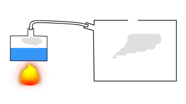
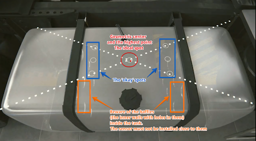
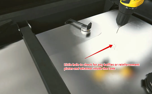
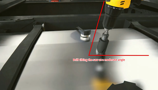
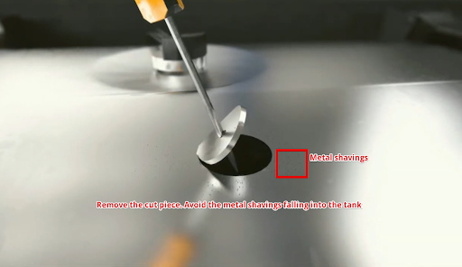


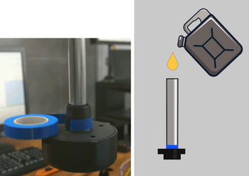
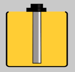

.png)


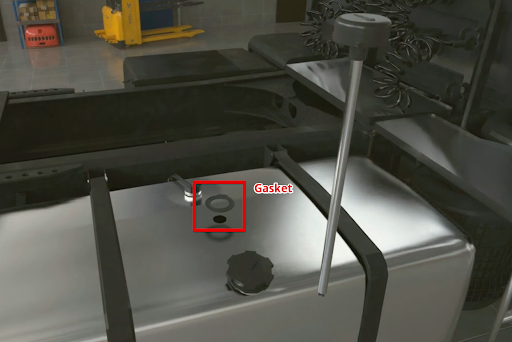
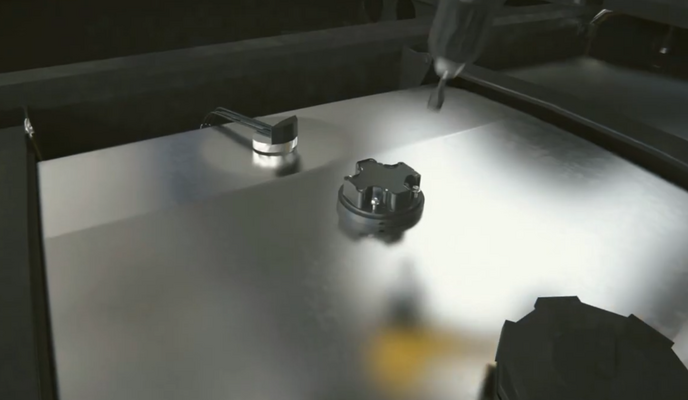


 You can also create a text file on your PC/Phone or manually record calibration


._.png)